ACRE wrote:
The LeMans had the intake pretty much straight with only one 30·
(?)
bend.
If you start to do more bends like Jerry's Russel application the
efficiency
must go down for the more work the air needs to go around the
bends.
When
you have to do different bends for for/aft rotor you will also
have
different flows even if the tubes are same length. How do you
compensate for
different intake tube shapes due to bends in the tubes.

Thomas J.
OK I have no idea. I guess the larger the bend radius the better.
I agree but we don't have the room for 16 to 18 inch straight
runners.
Perhaps in a helicopter.

Paul Lamar
Thomas,
Practical experience has shown that smooth curves have very little
effect
on flow. There is probably a slightly higher effect in a rotary due
to a
higher
average flow than a piston engine but not much. The manifolds that
have
worked for Mazda are very similar to piston manifolds with a
slightly
larger diameter. Many of the tuned intakes on new engines are very
curved. There is some loss of course, but usually the manifold can
flow
more than the engine can take anyway. For absolutely maximum flow
straight intakes are best but only if they fit in your cowl!
Bill Jepson
Jerry,
I had the same concerns as you have on the DIFFERENCE of the two
intakes -
it may not be worth worrying about, but for myself  I would go for the
intake with the same lengths, such as Paul's last design.
I played with different designs ( on paper) and came to up with the
same
outcome as Paul. At least the height is reduced, the bends are
minimum and
their the SAME LENGTH.
I'm wondering if you could bring the inlet from the side rather than
the top
?
BTW that discussion on inlet diameter/length was very informative -
thanks
to all concerned. Even though there may be disagreement on diameter,
I at
least know how things are worked-out.
Does anyone know the chamber volume area 12A,  if the 13B is 40 cu.
ins.
George (down under)
George,  I am going to build the 1.75 o.d. system which Paul has warned
me off of.   I like this system because it fits quite tightly over the
top of the engine.  The argument about runner I.D. cannot be resolved
with pen and paper.  If the 1.75 system does not develop the h.p.  then
I will build the Russell with 2 inch pipes.

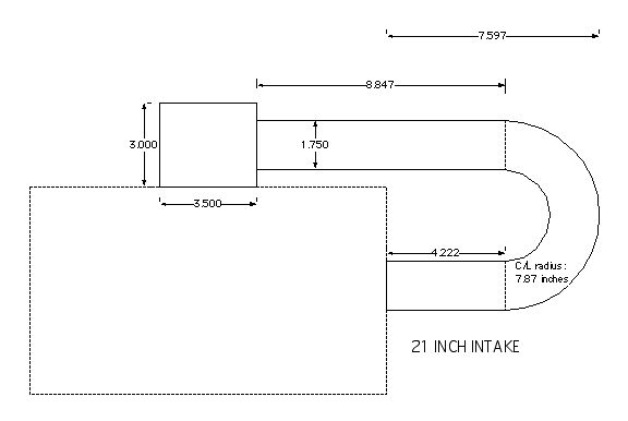
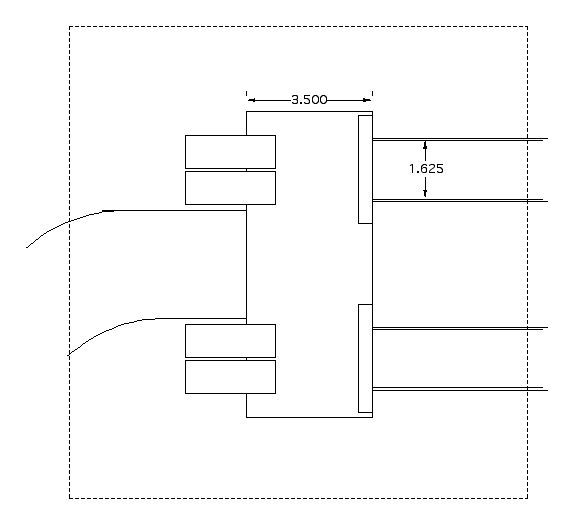
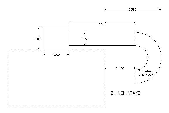
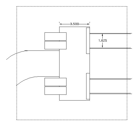
   I apologize for the crude drawings.  I was just checking things out.
The plenum i s centered on the engine and under the high part of the
cowl behind the spinner ring.  Ram intake curves toward the right cheek
inlet and does not block the dip stick.  The drawing is misstitled " 21
inch intake."   It is over 22 inches to the trochoide face.  This is
the maximum length achievable  with the plenum in the center. (Another
inch would be available by using tall bell mouths.)  Obviously. the
runners can be a lot shorter.  Rolf has suggested making the prototype
system with ground adjustable runners and I will do so.

   The drawing is off as far as the height of the runner above the
engine too.  I will lay the runners down to .125 clearance. The plenum
can be less tall.  As long as the bell mouths fit.  The ram intake tube
can be much lower, a rectangle like my exhaust pipes.  Regards,  Jerry
Opps dropped and image.

Paul Lamar

The Rotary Engine NewsLetter.  Powered by Linux.
ACRE NL web site. http://home.earthlink.net/~rotaryeng/
Copyright 1998-2004 All world wide rights reserved.