Douglas Fir wrote:
Hi Paul and everyone,

I have been making some educated guesses on power outputs on ethanol with a
slight boost for the 20B.  If a 20B is designed and operated at max rpm of
7700 with a 2.85 PSRU and C/S prop that would indicate prop speed at 2700
rpm on takeoff. I'm going to be conservative and guess the engine will
produce about 310hp a that rpm. At economy cruise of 155 Hp the engine will
be running at around 4000 rpm or less.  Remember we can adjust the prop
pitch. I am thinking now that the engine will have the high compression
rotors. That gives me the option to run gasoline or ethanol without  boost
if for some reason the turbo breaks.

For a good explanation of the two approaches to turbo compounding go to
Google, search for "Caterpillar electro turbochargers" and this PDF file can
be selected from the top of the page.

Caterpillar's ETC Turbocharger
< http://www.orau.gov...ession8/Hopmann.pdf tech

Both methods of turbo-compounding present pros and cons.

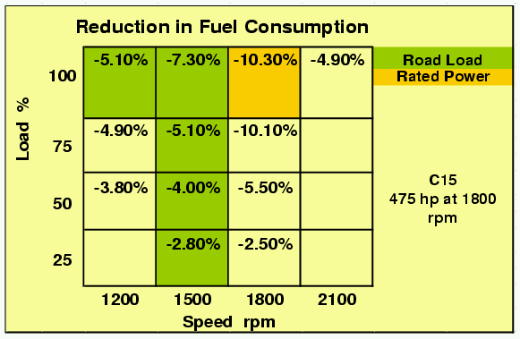
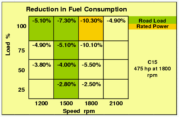
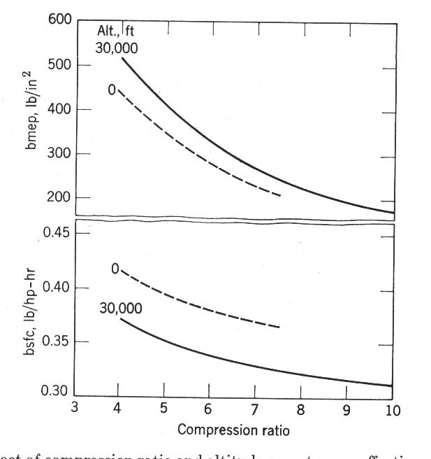
>From the chart we can see that the power requirements to drive the
compressor is around 18-25Kw (24 - 34 Hp) .
Bear in mind this data is from a diesel engine and the rotary exhaust being
more robust probably has more output. Care to make a guess for the 20B Paul?

 Interestingly enough a few points have become very clear to me. The turbo
is making a heck of a lot more power then I would have guessed. It is not
free spinning the compressor.  Although I knew the compressor did not have a
free lunch and must consume energy to compress air, I had imagined it didn't
need more than a few hp at 50% engine power rating.  Boy was I wrong!! In
fact it appears over and beyond the needed 24 Hp., there is over 10.7 Hp of
excess energy wasted out the gate.

I ran some numbers by our electrical generator designer yesterday and he
said a permanent magnet design based on our latest 99% efficient wind
generator, scaled up to put out 8Kw, would bring the total unit size
including housing, to about 6 inches in diameter and 5.5 inches long.
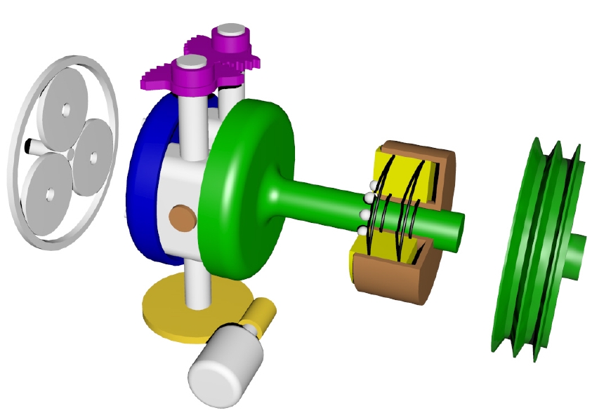
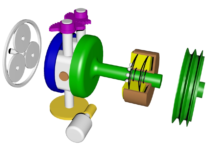
Permanent magnets motors output are limited by their magnetic flux density.
For a slimmer diameter motor it would have to be longer and have less (but
longer) magnets like the one shown in the PICT file. The  bottom line is a
generator that would weigh less than 13 lbs. That is the good news.

A thin motor large diameter motor that goes in the bell housing  would take
absorb the 3 phase  rapidly pulsed energy directly from the generator. It
replaces the geared flywheel and would be designed to become a generator as
well. Weight is still an issue because it depends on how it is mounted and
if that mounting plate can be milled to serve a dual purpose of the counter
weight and mounting plate. Probably 22 lbs or more..

Control switching at these low power rating allows us to use a current
switching device but the FETs that are robust enough to switch this fast are
expensive.

.....Looking at the chart again:

If we have an application that needs all of the boost like going for BIG
power in a little engine, then, we can only tap into the EXCESS power. In
this approach the 8kw generator and in housing motor and controls would
weigh the same or less than the components they replace. Gone is the
alternator, drive belt, flywheel and starter motor.  Perhaps an increase in
fuel mileage of 5%.  Looking at cost performance ratio......Yawn...

On the other hand lets say we are going after 95% of the power the turbo
produces which by the way increases with rpm.  At  50% rated power the
turbine is producing a total or more than 28kW or 37 hp.  Depending how much
boost we  actually end up needing with high compression rotors,.... not much
I suspect.... Paul's guess of returning about 30 Hp to to the eshaft at low
range rpm is correct.  BUT .....and herein lies the crunch.  If we want to
capture the bigger HP, in the electric hybrid manner, then the drive motor
within the bell housing either outgrows its house, or must become a high
voltage specialty motor. I suspect I could buy an airplane (or two) with the
cost of developing this particular motor and controls. The controller gets
big and heavy, and voltage climbs to over 300. It probably needs a buffer
battery as well.

Back to the drawing board:)

I think realistically we will have to use some sort of mechanical
compounding. Well sort of. Monty Roberts correctly pointed out, when I spoke
with him at Tracy's fly-in, that 40K would be too fast for a cogged belt.
That effectively rules out the double turbo experiment. That is fine because
it got me thinking again.

By using high combustion ratios rotors only a few PSI of boost can be
tolerated become combustion pressures exceed the seals limitations.
I am guessing the knock sensors tell us what that limit is and the SAAB
research with the spark plug sensors can confirm the approaching conditions.
That means the air compressor part the equation becomes significantly tiny.
So tiny that is could almost be eliminated (with P ports?) or changed to an
indirect (electric) drive system.  I have to do some actual research here
because using cost performance raises its head again.

For turbocompounding it would be nice if we could have one gearbox and a
simple connection to the water pump side of the  engine via a cogged belt.
Going back to my earlier  design notes I found a sketch I made of a gear box
with two outputs. The main output is for turbo compounding and the secondary
output for either a small compressor or electric generator.

The gear box mounts to the  turbo. Obviously the gear box needs to be oil
cooled and output pulley perhaps isolated thermally and vibrationally. In
this application without an inline electric generator it would be wiser to
select a turbine that can produce more torque at lower rpms. Lets say from
40,000 to 80,000 rpm tops.

Only two helical cut gears and a some high speed thrust bearing are needed
to reduce the speed in a 6:1 ratio transmitting  30 to 76tt0 HP out of the
gear box to the e-shaft at rpms from 6,700 low to high 13,400 high rpms. A
cogged pulley on the gearbox output and eshaft is sized to deliver rpms
about 10% - 15% higher than eshaft rpm, the rational being that the engine
with added torque will  stabilize at a higher rpm. The reverse is also true.
We all have experienced our auto engine slowing down when the air
conditioner comes on driving at high speeds. For pilots the engine slows
down when loading the prop. as when climbing.

The drive belt speeds are within the design limits of a fiber impregnated
cogged belt drive if we compare it to the belts speeds and power transmitted
to superchargers. I haven't looked at hard data yet and admit this is the
weakest link of the idea.  We may have to go gears all the way if we want to
capture the upper 70 hp. limit.

An interesting fact is that the amount of turbo power available increases in
proportion to the amount of shaft rpm of the engine.  This means if we want
to keep the gear box output within a 10% or so higher range we have to slow
the turbo down when it is running at top rpm.

If we have a C/S prop though it probably isn't even a issue to worry about
unless you are racing flat out.

Another idea is to use a more efficient turbine with adjustble vanes thus
controlling the turbine blade pitch and hence speed.

The beauty of this turbo compounding layout is that it is compact, and
allows for full range turbo-compounding without waste gates. Sleek planes
will get more benefits at higher speeds. We can now select a turbine  that
is most effective for driving a gear box not a compressor.

 An over boost safety valve should stay in the engine intake system and  be
interfaced to the energy source driving the compressor.

 A hint for all of the above thought processes came from realizing it is
easier to control excesses than to deal with controlling the whole load. I
have a generator now and it is rated up to 1.8Kw.  It puts out (your choice)
12, 24,48, or 84 volts. The controller is palm size. I have both already.
Grant money from Japan government supported the development. If you are
interested, ask me to send a picture directly. Seems I just can't get
totally away from the electric generators and motors huh?  Might as well
make the two means of providing charging energy more flexible in their
function. The slim in-housing starter motor is still in development in
Arizona and will be finished next spring. If the concept is bullet proof
(after two years of testing) I will provide components to the homebuilt
market.

Speaking of photos, can anyone tell me how to convert large res. JPEG photos
to a smaller size without compressing them?  The curator of this site gets
very cranky when I send him 1 meg photos:)

Getting ready to get ready.

Doug in Japan.
Doug sent a pdf but it is too big to publish.
This Cat chart confirms what I have been saying all along. Electric turbo compounding
will never equal the efficiency of mechanical turbo compounding. The R3350 TC achieved
a 20% decrease in BSFC 50 years ago. 10% is hardly worth the cost increase.

Paul Lamar

The Rotary Engine NewsLetter.  Powered by Linux.
ACRE NL web site. http://home.earthlink.net/~rotaryeng/
Copyright 1998-2004 All world wide rights reserved.