These are my wild ass guess of the HP consumed by a prop as a
function of
the RPM looks like. They arer in no way quantitative at this
point. It
could
be some other math function and may in fact not be so simple.
Due to the fact that tips of the prop approach supersonic velocity
and
a consequently steep drag rise the shapes of these curves could be
far
different.
I am hoping Vance can come up with some prop HP consumption
figures
based
on
his computer simulations.

Paul Lamar
Paul and others - I think this is somwhat like what you are seeking.
The
HP
and
torque curves are plotted with EXCEL and are against a 2.85
reduction
(torque
is foot lbs at the engine and HP is at the prop. The prop load
curves
are
for
a simulated 73 in dia with 115 in pitch for a 240 mph plane, blade
area
is
set to absorb appropriate power at that speed. the static and 130
mph
(climb)
power curves run in a terrible pit of low HP this 2.85 reduction
appears
not good on a fast plane static is almost hopelessly stalled and
power
has
not
really come on for climb. Variable pitch is really needed to make
this a
happy
set up. - Vance
We are on to something here Vance.  What does it look like set to
230 MPH and 68 inches?

3 blades perhaps?

What flat plate drag does this work out to?

Great work. Exactly what we are looking for. Thanks.

Paul Lamar
Paul - I have a problem understanding why you want a smaller prop dia.
With
the
2.85 reduction and the curves you have provided, the tip speeds are very
modest.
Smaller diameter is going to have a perf penalty everywhere, and most
heavily
at static and climb. These curves show a dreadful power cave in right at
those
operating points. This would almost force a controllable prop with all
it's
cost, weight and complexity.
The new curve is a bit cleaner, and shows that the smaller prop is a bit
easier to spin at static, but the crummy disk loading provides less
thrust
even tho the engine is cranking a bit more HP. At design point the two
props are a wide single curve - noise would be down, but I have trouble
seeing any other good side to this.
240 mph would be about 2.5 eff flat plate which would be a very clean
Cruiser, or an average composite retract of similar size. The number of
blades
has virtually no impact on preformance - the wake losses wipe out any
gain
>from higher aspect ratio blades. - Vance
Thanks again for this work Vance. As I suspected the climb and the top
speed curves move closer together.

Well that is what we want to find out. It might be cheaper to build
a variable runner length manifold than to buy a constant speed prop since
gear boxes
with governor drives are either very expensive or unavailable.

I would not exactly call 150 HP at static and about 175 HP for climb a
"dreadful power cave in" for what amounts to a top speed prop.
Particularly on such light weight airplanes like the RV4, RV6, RV3,
Tailwind, etc.,
etc. Most two place experimentals don't need all that much climb HP. The
four place
airplanes really need a constant speed prop to get max performance.

If climb is a priority one can always buy a lower pitch climb prop of
course.
Broadening the HP curve can be simply done on the side port engines at the
expense
of peak power by using longer runners for the small center ports.
We are rapidly expanding our options here with all this manifold R&D.

So far rotary engine manifold design has been hit or miss with people
winding up
with runners that are too long or too small for top speed. This is
partially due
to the limited amount of room on the top of the engine and dealing with
the oil filler and dip stick that just happen to be were the plenum needs
to go.

Most people claim better climb performance and a top speed hit with three
blade
props.

BTW do you have the formula you use for calculations and plotting these
HP curves as a function of prop RPM? Also  have you added altitude
as a prop design variable to your program?

Paul Lamar
The program that is used utilizes an iterative matching of results between
a momentum disc assumption and a strip element calculation that uses
airfoil data and blade area against flow velocity through the disc. Hundreds
of loops per point. It is written in BASIC, and can be made available tho
not completely intuitave to run. It can be run for any reasonable altitude.
It does not recognize any sonic effects. Results are printed in tabular
form, and at present I transfer the points manually to EXCEL for plots.
Vance
I can handle the source code. QB or VB? What rational does Paul Lipps use
for his plan form? My guess is constant HP per blade element.

Paul Lamar
The program Vance is talking about, and that Paul Lipps uses, is the
same program I use. It's from the book "Modern Propeller and Duct
Design" by Martin Holman. I think in the Contact article it said he is
using an eliptical wing shape as the most efficient, and then varying
the chord along the elliptical wing, to compensate for the different
velocities along the "wing" (blade). Something like that...

Perry
I think Vance wrote his own. In fact I know Vance wrote his own as it was written
well before Martin published that book. There are a lot of things that change
along a prop blade not the least of which is the Reynolds number. Vance
and I agree... Paul Lipps is probably looking for a constant HP consumption for each
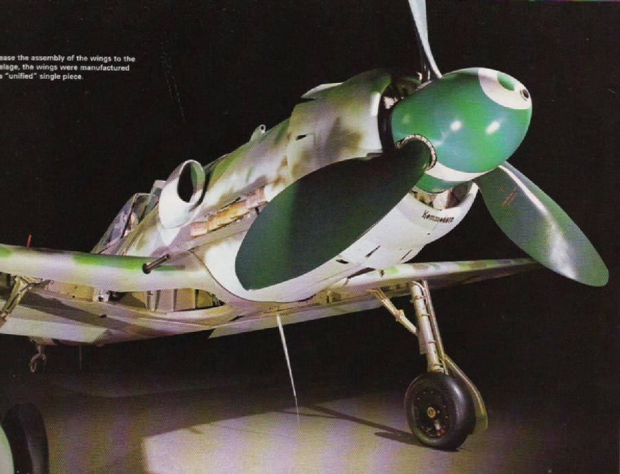
radial blade element. HP is drag times speed. BTW the Germans had some rather
unusually looking prop blades back in WW II. Check out this Focke Wulf.

Paul Lamar

The Rotary Engine NewsLetter.  Powered by Linux.
ACRE NL web site. http://home.earthlink.net/~rotaryeng/
Copyright 1998-2004 All world wide rights reserved.