Small diameter tubes fill the intake chamber better at low RPM than large
tubes. That is why Mazda uses multiple small diameter tubes for cars. We
are
not using the Mazda engine to power cars in case you haven't noticed. We
don't
need low RPM engine torque! This is a recording.

The most powerful wankel engine will have both peripheral and two side
ports of the
largest possible total area given the restrictions on port timing.
Paul Lamar
snips..
We have two examples of P-port engines generating close to 300 HP tested
on dyno's with two inch runners. One of which with fixed length runners
dominated road racing road racing in the US for a decade where low speed torque
and engine response was and still is absolutely essential. Then P-ports were more or
less outlawed in US road racing as too powerful. Not fair to piston engines.

Paul Lamar
I might add that dozens of these P-port engines were built in that decade if not hundreds.
These engines spent thousands of hours in total on the dyno looking for
a few HP here and there. Many of those hours were done at Racing Beat and other
rotary engine shops around the country.

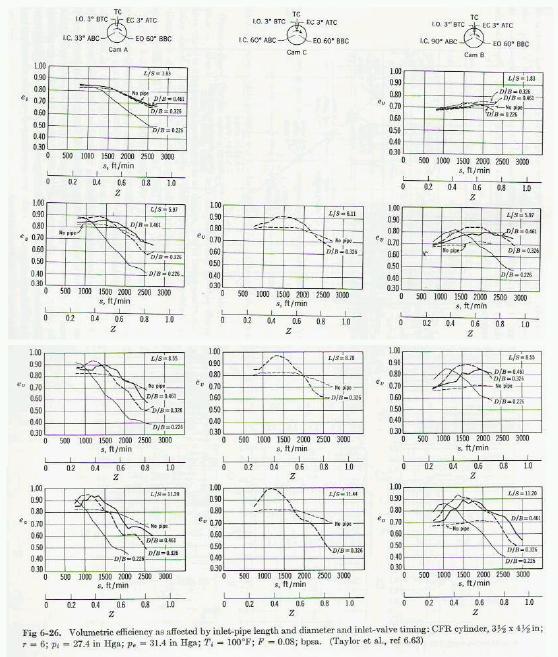
Here is some back ground info from Taylor on the complexity of tuning piston
engines. Note that at high speeds the effect falls off and shear port area dominates.

Z is the mach number in the pipe. D is the diameter of the pipe.
B in the case of the rotary is the area of the rotor face.
Unfortunately little else can be found that is analogous to a piston
engine. The intake p-port of the rotary is open nearly 100% of the time
While that of a piston engine is open only 25% of the time.
Never-the-less Mazda engineers have done enough fundamental research
to develop a theory that allows them to make large gains in VE.

If you guys can come up with more HP at 6000 RPM (240 HP) than the Mazda engineers
did with the Le Mans p-port engine design I will eat my words.

The time has come to put up or shut up. When the flag drops the BS stops!

Paul Lamar

############################################################################
AIR CAPACITY OF FOUR-STROKE ENGINES

EFFECT OF DESIGN

Inlet-System Design. It has long been known that high volumetric
efficiencies can be obtained at certain speeds by means of long inlet pipes
(see ref 6.6-). The effects noted are caused by the inertia and elasticity
of the gases in the inlet pipe and cylinder.  Figures 6-26 and 6-27 show the
effect of various inlet-pipe lengths and diameters on volumetric efficiency.
These tests were made with a single cylinder engine, with a short exhaust
pipe, and with large surge tanks at the end of the inlet and exhaust pipes.
Complete theoretical treatment of the relation of inlet pipe dimensions to
cylinder dimensions is beyond the scope of this volume. A comprehensive
experimental and analytical treatment of this subject is given in ref 6.63.
The following general relations are important:

1. If viscosity effects are assumed negligible and, if similar engines have
similar inlet systems, the effects of inlet dynamics on volumetric
efficiency will be the same at the same piston speed, other operating
variables being held constant. This conclusion also applies to engines of
different stroke-bore ratios, provided the cylinder design is otherwise the
same and the ratios pipe-diameter-to-bore and pipe-length-to-stroke are held
the same. Thus, the curves of Figs 6-26 and 6-27 should apply over the
useful range of cylinder size and stroke-bore ratio.

2. The dynamic pressure at the inlet port at the end of induction is the sum
of effects caused by "standing" waves which have been set up in the inlet
pipe by previous inlet strokes and the effects of the transient wave set up
by the induction process.

3. There are no sudden changes in the volumetric efficiency curves at points
at which the "organ pipe" frequencies of the inlet pipe are even multiples
of the speed of revolution.

4. Long pipes with small ratios of D/B give high volumetric efficiencies at
low piston speeds because high kinetic energy is built up in the pipe toward
the end of the induction process. At higher piston speeds, the flow
restriction offered by small D/B ratios becomes dominant and volumetric
efficiency falls.

5. Long pipes with large ratios of D/ B show maximum volumetric efficiencies
at intermediate piston speeds due to kinetic energy built up in the pipe. At
high piston speeds the air mass in such pipes is slow to accelerate, and
volumetric efficiency falls off.

6. As pipes become shorter, the maximum gains in volumetric efficiency over
that with no inlet pipe grow smaller, but the range of piston speeds over
which some gain is made grows wider.

7. Figures 6-26 and 6-27 should be of assistance in selecting the best pipe
dimensions for a given type of service.


The Rotary Engine NewsLetter.  Powered by Linux.
ACRE NL web site. http://home.earthlink.net/~rotaryeng/
Copyright 1998-2004 All world wide rights reserved.