Notice the length of the pipe on the piston engine was
50 inches
long for 2500 RPM and the optimum length on the Le Mans engine for 6000
RPM
was 16 inches long.

We are nowhere near a workable theory for rotary engines. I am just
pointing out
some similarities with piston engines. Don't try to read something into
this that
is not there.  All of this is empirical. Determined by extensive
experiment on one piston engine of a given bore and stroke. The work done
by Taylor
is sure to scale only to piston engines. You keep sounding like you are
going to come
with a magical number for the pipe diameter and length. We have a long way
to go
to come up with a workable theory for rotary engines. Forget it. The only
way you are
going to do that is by extensive experimentation on a dyno. Build the
dyno.
Why bother anyway? The solution is staring you in the face. Mazda has done
it for
you. Nobody anywhere has a built a rotary engine with something other
than 2 inch p-port pipes that comes close to the 240 HP at 6000 RPM
achieved by the
the Le Mans engine. Copy the Le Mans engine exactly. What is it about this
that is
so hard to understand.


BTW Why mess with a ancient 12A engine? It is no lighter than a 13B.

Paul Lamar
One of the major differences involved with intake tuning for a Wankel is the
shape
and duration of the "suction" pulse as related to the frequency of those
pulses.
The Wankel case is analogous to hooking all the intakes to a single pipe
for a 3 cylinder piston four stroke.  This probably has the effect of
reducing
the "sharpness" of the resonant peak. Obviously tuning works, as evidenced
by the Le Mans engine. Resonant devices are characterized by a "Q" factor
of resonant efficiency - the opposite of damping. Both "organ pipe" modes
and cavity modes (Helmholtz cavities) can be used to support resonance
(or disonance - untuned wave damping") .
If you look at the ranks in a pipe
organ you can see that length/diameter ratios are a factor in the "Q". A short
length to diameter ratio has poor "Q" since it begins to support other modes
such as radial and circumferential to the detriment of the longitudinal that
you are trying to use - ie larger diameter is not always better.
That is my nickel on tuned pipes - for whatever it is worth (we get exposed
to a bit of this sort of thing when trying to suppress destructive acoustic
instabilities in rocket combustion) - Vance
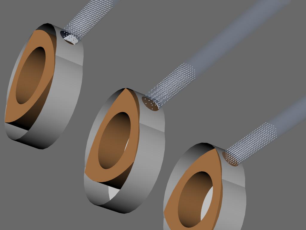
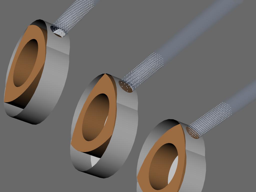
Here is my crude attempt at illustrating what happens in the first instants
when the p-ports starts to open. Air has elasticity, adhesion and inertia.
In Fluid Mechanics adhesion is defined by viscosity I think.

Start at the lower right and work up to the upper left.

When the port is  closed the air in the pipe is a homogenous stationary mass
at atmospheric pressure.

As the port starts to open a reduction in density and pressure occurs near the port
because the main mass of the air has inertia. The reduction in air pressure
causes the main mass of air to accelerate towards the port.

That is all that I have modeled so far as it takes a long time for my one gigihertz
CPU to render these illustrations :) It is also time consuming to do the
illustrations in the first place.

As time progresses the intake chamber starts to fill and the pressure rises
in the intake chamber towards atmospheric pressure. The inertia of the main
mass of air keeps moving but starts to slow down as the dynamic pressure of
the moving air begins to equal and exceed the static pressure in the intake
chamber. It then stops moving.  If the pipe  is the right diameter and length
this happens just about when the port starts to close. The pressure in the intake
chamber is now about 20% higher than atmospheric. The timing of these events depends
on a lot of factors not the least of which is the pipe diameter and length.

It is also perfectly synchronized at just one RPM. It also depends on the
properties of the air which change with temperature and altitude.
therein lies the potential of the variable length system to optimize
cruise BSFC at any altitude. High VE translates to low pumping losses
resulting in more net HP out for a given amount of fuel burned.

Taylor's explanation of what happens in an intake system is worth reading over very
carefully so here it is again. Vance, note his comments about organ pipes.


Paul Lamar

The Rotary Engine NewsLetter.  Powered by Linux.
ACRE NL web site. http://home.earthlink.net/~rotaryeng/
Copyright 1998-2004 All world wide rights reserved.
AIR CAPACITY OF FOUR-STROKE ENGINES

EFFECT OF DESIGN

Inlet-System Design. It has long been known that high volumetric
efficiencies can be obtained at certain speeds by means of long inlet pipes
(see ref 6.6-). The effects noted are caused by the inertia and elasticity
of the gases in the inlet pipe and cylinder.  Figures 6-26 and 6-27 show the
effect of various inlet-pipe lengths and diameters on volumetric efficiency.
These tests were made with a singlecylinder engine, with a short exhaust
pipe, and with large surge tanks at the end of the inlet and exhaust pipes.
Complete theoretical treatment of the relation of inlet pipe dimensions to
cylinder dimensions is beyond the scope of this volume. A comprehensive
experimental and analytical treatment of this subject is given in ref 6.63.
The following general relations are important:

1. If viscosity effects are assumed negligible and, if similar engines have
similar inlet systems, the effects of inlet dynamics on volumetric
efficiency will be the same at the same piston speed, other operating
variables being held constant. This conclusion also applies to engines of
different stroke-bore ratios, provided the cylinder design is otherwise the
same and the ratios pipe-diameter-to-bore and pipe-length-to-stroke are held
the same. Thus, the curves of Figs 6-26 and 6-27 should apply over the
useful range of cylinder size and stroke-bore ratio.

2. The dynamic pressure at the inlet port at the end of induction is the sum
of effects caused by "standing" waves which have been set up in the inlet
pipe by previous inlet strokes and the effects of the transient wave set up
by the induction process.

3. There are no sudden changes in the volumetric efficiency curves at points
at which the "organ pipe" frequencies of the inlet pipe are even multiples
of the speed of revolution.

4. Long pipes with small ratios of D/B give high volumetric efficiencies at
low piston speeds because high kinetic energy is built up in the pipe toward
the end of the induction process. At higher piston speeds, the flow
restriction offered by small D/B ratios becomes dominant and volumetric
efficiency falls.

5. Long pipes with large ratios of D/ B show maximum volumetric efficiencies
at intermediate piston speeds due to kinetic energy built up in the pipe. At
high piston speeds the air mass in such pipes is slow to accelerate, and
volumetric efficiency falls off.

6. As pipes become shorter, the maximum gains in volumetric efficiency over
that with no inlet pipe grow smaller, but the range of piston speeds over
which some gain is made grows wider.

7. Figures 6-26 and 6-27 should be of assistance in selecting the best pipe
dimensions for a given type of service.