Alan Tolle wrote:
Paul, occasionally a question comes up which I think I should
respond
to,
since I know more about it than anyone else.

Powersport under Everett Hatch used a clone of the Bendix manifold
pressure
controlled mechanical fuel injection system that was created by
Don
Rivera
at Air Flow Performance specifically for him --- the same fuel
injection
system that has flown millions of hours on Lycoming engines.  The
modification was separation of the air pressure measuring system
from
the
fuel metering system, the former being incorporated as the air
intake of
the plenum, the latter being linked to the throttle plates.

Injectors were one per cylinder just like everything out there
flying
with
fuel injection.  Injectors were at first screwed simply into the
oil
injection ports, later were positioned in the intake runner bend
so
that
they pointed directly at the throttle plates. The latter worked
very
well. And as you remember the positioning of the throttle plates
right
at
the trochoid housing completely solved the problem of idle
roughness at
low
engine rpm.

Some might object to the injectors being on the hot side of the
engine,
but
if you shroud the exhaust system in a stainless steel heat shield
as
you
should there is no problem.

You are aware that we spent a lot of hours on the dyno tuning the
intakes,
varying both length and diameter. The result was 20% more
horsepower
more
or less free --- and much less complicated that a turbo. > > Alan
Tolle.
Alan,
I read your e-mail with much interest and would like to thank you
for
that
information - it all helps!

I do however have a question that has been niggling me for some time
and the
answer hasn't been crystal clear to me. The question is- is it the
butterfly
close to the port that fixes the rough idle or the injectors close
to
the
port OR BOTH.

I'm wondering if we take the injectors to the other end, do we
sacrifice
idle at the expense of better atomisation and BSFC.

In other words is it the butterfly alone at the 'coal face' that
fixes
the
idle.

Another question Alan, what size  diameter pipes did power sport
use in
their inlet manifold

George ( down under)
Alan Tolle wrote:
George

The throttle plates on a peripheral port  13B engine must be right at
the
intake opening of the trochoid housing if one expects anything in the
way
of a decent idle  below 2000 rpm.  The area is being cooled by
incoming
fuel and surrounding water jacket so it is not really hot right there
 The
nearly completely closed throttle plates prevent residual exhaust
gasses
from becoming mixed with the intake charge.  When mixing does occur
(throttle plates at the other end of the runners)  that mixing
produces a
very uneven three-to-one lean misfire which can lead to complete
engine
stoppage.

There are several things to keep in mind.  First, 2500 rpm is a
perfectly
acceptable idle for a race car, however:

Wood props, as are and will be used on most rotary installations,
have very
little rotational inertia (flywheel effect) so they stop much easier
than
might a metal blade.    The lean misfire encourages the engine to
stop, and
every pilot's worse nightmare is engine stoppage at idle on short
final.
Those same wood props are probably going to be pitched more for
cruise (we
all want our airplanes to be fast)  so the idle rpm is going to have
to be
as low as possible --- just try to land a cruise pitch prop turning
at 900
rpm.  In most aircraft you will float forever.

The location of the injector nozzles themselves is less critical.  As
I
noted we first screwed them right into the holes in the trochoid
housing
originally used for the apex seal oil injection (we ran two cycle oil
in
the gasoline  in the ratio of one ounce of oil per gallon of gas.)
Then we
welded a bung onto the outer radius of the intake tube oriented to
point
the injector right at the throttle plate.  The latter location seemed
to
work better.  Think about it --- the fuel can never puddle at the
throttle
plate because in essence the "intake valve" is always open.

I don't know if fuel injection nozzles on a peripheral port engine
can be
located back at the plenum, or whether this location might improve
BSFC,
but I suspect negative for both.  I also suspect that sending a
fuel/air
mixture around a 180 degree bend is going to result in some fuel
plating
out on the outside of the radius with resulting mixture leaning at
certain
rpm's.  We have actually experienced this type problem in other
applications.

Probably the greatest effect on the BSFC is the capacity to lean with
altitude so as to keep the EGT's as high as possible all the time.
This
occasions two things --- a very robust first foot or so of the exhaust
system and careful attention to how you are going to get the
additional
heat out of the cowl.  Both are do-able.

Finally, in answer to your, question the intake tubes on the 180SL
engine
were 1.5 inches in diameter and 22 inches long.  I still have a set
of them
in my hanger and I went out and measured.  These numbers gave us best
power
on the dyno.

Hope this helps.

Alan Tolle
Jerry Hey wrote:
Thank you Alan,  This information is so valuable and fascinating.  Our
calculations on runner length and I.D. came out at the same place.   I
have my fingers crossed on injecting into the bell mouths. This has
been done on rotary engines in RX7s  and it is claimed they run very
strong  but I don't know if they were using 180 sweeps.  I would think
not.   They were definitely not P Ported.   My throttle body has
sufficient material to install the injectors directly aimed at the
butterfly.  That is what I will try next, following  your example, if
plan number one does not work.  I wish every day for only one injector
per rotor.  That would make things so much easier.        Regards,
Jerry
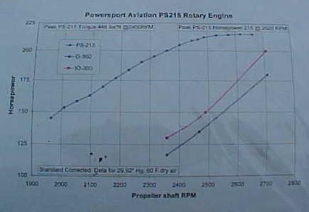
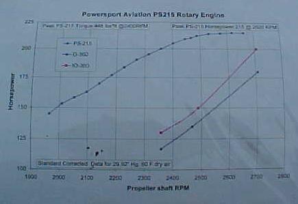
I want to point out yet again and for the umpteenth time the max power Power Sport
ever saw was 215 HP at 6000 RPM  while the Le Mans engine p-port  in two rotor
form was was 240 HP at 6000 RPM. Frankly I don't think many people will spend
the extra money nor take the risk for only 15 HP over a well ported side port engine.
If I were doing it I would up the size of the pipe a 1/2 inch and shorten it a few
inches. That is a real cheap 25 HP. Besides that I would have 270 HP at
7500 RPM if I choose to go with a 2.85:1 gear box. I cannot say what HP
one would get at 7500 RPM with only a 1.5 inch pipe. The HP curves I have
for the Power Sport engine with a 2.4:1 PSRU are flat at 6000 RPM indicating
a fall off in the breathing. It would be nothing short of dumb to use 1.5 inch
pipes with a 2.85:1 gear box.

BTW the curves below the HP curve are prop load curves for Lycoming engines.
A combination of what HP the engine will put out when confronted with a fixed
pitch prop load. In contrast the HP curve above it was full load at all RPM's.
Apples and oranges. All HP above prop load is useless and unobtainable with
out a constant speed or variable pitch prop.

Paul Lamar

The Rotary Engine NewsLetter.  Powered by Linux.
ACRE NL web site. http://home.earthlink.net/~rotaryeng/
Copyright 1998-2004 All world wide rights reserved.