I was kind of curious about what happens to a turbine
when you make it smaller and smaller. I discovered this paper at the
UCLA engineering library today. Looks like we will have no
problems. This 1/2 inch diameter compressor still had
65% efficiency at 420,000 RPM.

I am going to contact some of these guys and see if we can get
some academic help for a very worthy cause. Namely 20% reduction in the
worlds use of gasoline for cars. In the mean time we will learn
enough to make some turbo compound rotaries for our use
in airplanes.

Paul Lamar
Paul

I believe I gave Monty a paper on small micro turbines made at MIT. If you
are interested perhaps I can dig it up.
They have it at UCLA so if you give me the number I can copy it.
Correct me if I am wrong. The friction wheels idea is your concept?  It
seems to me that the 'wheel' would slip when it heats up because although
the material is the same the mass and the dimensions of the outer ring and
the inner wheels are quite different.
The Paxton worked fine. So does a locomotive.
What was the reason the gears wouldn't work? line speed over limit.
Yes. Line speed was twice over the limit. Lots of wind age in the bargain.
Did you specific helical or spur when you were designing the first one.
helical is smoother and quieter, spur noisier but perhaps stronger.
All they made in a suitable size was spur gears as I recall. I put a lot
of research into the gearing before I gave up. Most of it is in the
old messages.
Lets see  if the small gear was held to 1" in a module 1.5 category then we
would have to have a special one made.

1" x 3.146 =  3.146 x 100,000 rpm =  (314,600/12 = 26,216 ft/min.

The NASA tech brief on high speed boxes for aerospace gear boxes stated that
designers prefer to limit their gear line speed to under 26,000/ min so we
are right on the edge.  Size was another factor as well as I remember.  The
outer ring was becoming 240mm in ID. diameter.   Perhaps a 3/4 inch gear
would be better. If we go with a axial turbine it might be better to go to a
double step planetary like motor gear boxes.

For 15hp out at 100K that is what 0.78 ft/.lb in the pinion gear?

12/1 reduction is 8300rpm  It is possible to play with a pulley and belt
from there.  Use a  CVT in research to nail the best rpm. as is to heavy to
fly with.

Weight wise I would have to think about it. Turbines are lovely but tend to
be narrower band devices and I am only guessing here... not as robust as the
TE-04 animal.

Still I am open to the exploring it.

Doug in Japan
Both are turbines. We need to refer to them as radial flow (turbo chargers)
or axial flow (common in jet engines.) The efficiency are about the same.
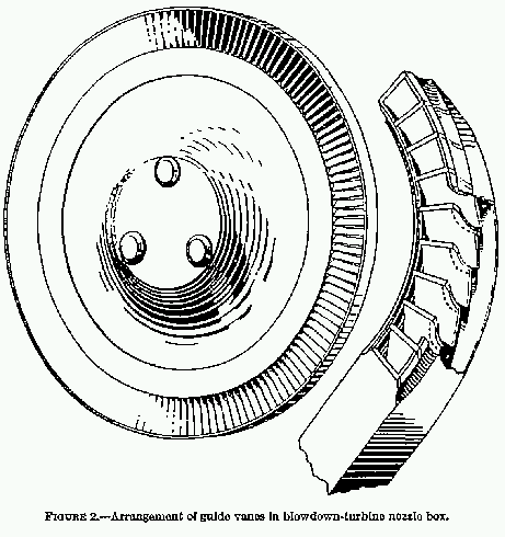
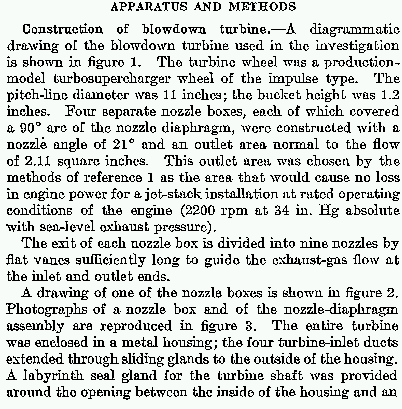
Naca got 70% efficiency (21% of engine HP at altitude and 9% at SL) by
grabbing an axial flow turbine from a supercharger they had lying
around and hooked it up to an engine they had lying around.
Probably took them a couple of days. No CFD. The nozzle was designed
arbitrarily and crudely made. That's looks about right. Down load
NACA Report 768 in pdf form from http://naca.larc.nasa.gov/
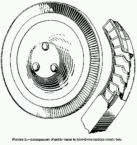
Here are a few scans.

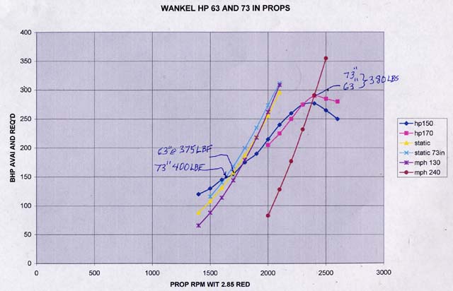
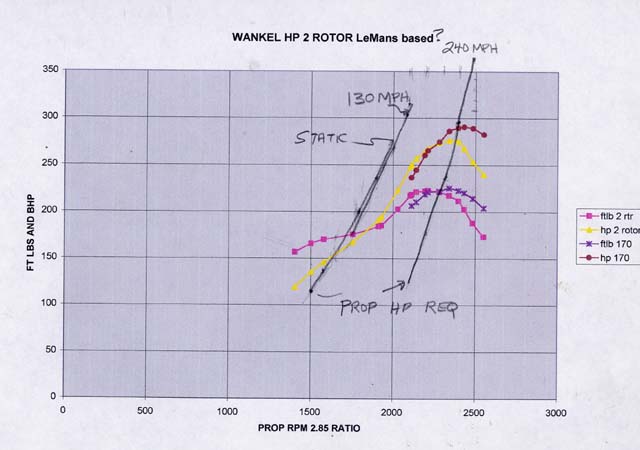
You don't need the CVT for an aircraft. The R3350 TC got along fine without
it. A CS prop will help greatly. CS mean constant RPM out of the engine
with therefore constant HP out of the engine. A fixed pitch prop gives
max HP out of the engine at an RPM that varies with altitude. In other
words HP in a free breathing rotary (and an aircraft engine) is a slanted
straight line while a fixed pitch prop load is a vertical line. Where the two
intersect is the point design. You can move the prop load line left and
right by changing the pitch. The point design will then move up and
down the slanted line increasing or decreasing the HP obtained out
of the engine respectively.

Here is Vance's plot of the situation.

The Wright brothers did not take no for an answer.

Paul Lamar

The Rotary Engine NewsLetter.  Powered by Linux.
ACRE NL web site. http://home.earthlink.net/~rotaryeng/
Copyright 1998-2004 All world wide rights reserved.