Douglas Fir wrote:
Paul

I must admit I was getting confused for awhile wondering if you are
speaking about auto or aircraft applications steam injections and model jet
engines:)

I read NACA report 786  report by the way. Thanks.  Very interesting that
this work was done in 1943.

Monty made some good points about large blow down turbines. It would be time
consuming to develop compared to playing with the tons of radial turbines on
the market or laying around the junk yards.

OK let me confirm this I should be looking for a Garrett T04 or T45 to
modify.

Below is your post from a few weeks ago.
Had a long talk with my friend at Garret now Honeywell and
he gave me a few tips. Make sure you use a ceramic ball bearing turbo
charger
and don't put any side load on the shaft itself. The biggest problem
they have is the whirl vibration mode of the shaft. The ceramic ball bearing
shaft systems are much stiffer and that problem goes away more or less.
He also confirmed the TO4 or the even larger T45 would be the right
starting point.
For 30 to 55K operational ranges?
He also gave me some contacts to get some turbine maps of flow verses
efficiency and pressure ratio for existing products. The A/R to use for a
given
radius is not necessarily the highest. Turbine blade angle is
varied to optimize it for flow and pressure ratio. One turbine
[blade]?
design is used with a wide range or A/R housings to adjust the turbo charger
for
a given engine configuration. Therefore a change in the A/R makes small
single
digit changes in the efficiency.
I realize I am going to have to test a lot of different housings and turbine
rotor design to optimize it.

What site can I go to get size, weight data?

And oh yes... Thanks for getting the book on ethanol production.  I would
love to see it.

Good news.  My brother says he may have found an old electric prop
controller and props from an 1950s era Bonanza.  He said I could trim them
down and use them for a C\S (manually operated) for testing the engine on
the dyno.  I also have a manual transmission on hand. One of the speeds
ratios is close to 1:1. Could I use this as a dyno unit PSRU?  I would
rather not stress out a new PSRU until the design components are finalized.

doug in Japan
I think you are being very optimistic on the 30 to 55K. It appears the rule
of thumb is the gas speed must be twice the blade speed.  I have not figured
it out yet but you can do it yourself by converting the 24 pounds per minute
mass flow to cubic feet per minute and then figure out what the scroll area of
the TO4 turbine is. That is the easy part. Here it is. The turbine wheel
diameter for a
TO4 is either 2.992 or 3.111. As a first guess the the R in A/R is therefore
about 2.5 inches. For an A/R of one that means the area of the scroll is
also about 2.5 square inches. The part number for the .96 A/R TO4 turbine
housing is 407414-0021 trim O or 407414-0031 for trim P.

The question is;  what is the exhaust velocity of the gas passing down a 2.5
square inch pipe when the mass flow is 24 pounds per minute and the
temperature
in absolute terms is 2000 degrees K? Once you know that you will know the RPM
of
the roughly 3 inch in diameter turbine. Check back in the earlier messages.
Vance thinks it is 440 feet per second but I am not so sure as we have data
from Francois showing a TO3 turbine rotating at 130,000 RPM and 440 feet
per second won't do that. I think the gas velocity is much higher than
that.

The transmission will work.

Paul Lamar
Thanks Paul,

I was assuming 55K would work because that is the maximum speed of the
second turbine used by Scandia.  We don't know the size but the illustration
shows it as being similar size as the primary turbine.
Here is the URL.

http://www.westwardscania.com/trucks/NTR/technology/turbocompound/how_does_i
t_work.asp?ComponentID=43343&SourcePageID=56704#2

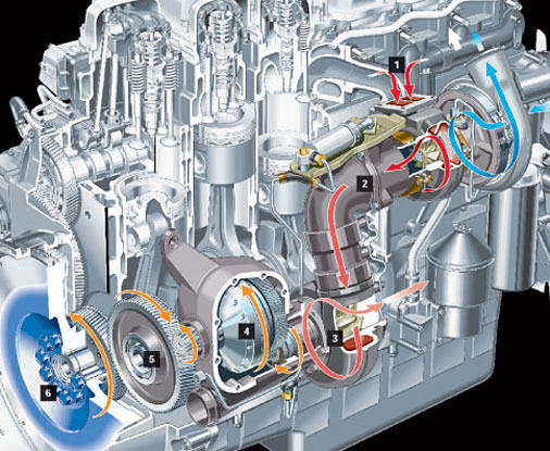
Here is the data. Note that the diesel has lower gas temp. and most likely
lower gas velocities as well.  That should give the RE engine an better edge
right?
1. Input of exhaust gases from the manifold, at a temperature approaching
700ºC [1292 F].
2.    Exhaust gases are used to drive the conventional turbocharger, where
energy is used to boost power and torque in the combustion process. These
exhaust gases, instead of being lost to the atmosphere, are then directed to
the turbocompound unit.
3.    The exhaust gases, on reaching the turbocompound unit, are still at a
high temperature (around 600ºC) [1112 F]; the energy is used to spin the second
turbine at up to 55,000 r/min. After passing this point, the gases are down
to below 500ºC [932 F], and are expelled via a conventional exhaust system and
silencer.
4.    The revolutions of the turbine are stepped down in various stages by
mechanical gears and a hydraulic coupling. The hydraulic coupling balances
out variations between the rotation of the flywheel and the turbocompound
turbine.
5.    By the time drive reaches the crankshaft, the rate of rotation is down
to around 1,900 r/min.
6.    The flywheel's momentum is increased, and its rotation becomes more
stable and even.

I am trying to track down an engineer who is familiar with that project to
speak with him.

Doug in Japan
----------------------------------------------------------------------
"Scania turbocompound;
Turbocompounding creates extra power by converting "wasted" energy.

Turbocompounding seems to defeat the laws of physics by creating energy out
of nothing. It works by recovering energy that would otherwise be lost, or
wasted. It is a classic example of recycling. Instead of expelling "wasted
energy" via the exhaust pipe, more heat is extracted from the exhaust gases
by a second exhaust turbine downstream from the turbocharger.

The second turbo (the turbocompound turbine) spins at 55,000 r/min. This
motion is passed through turbine gears and a hydraulic coupling, then
through the timing gears to the crankshaft. Stepping down the revs produces
a useful boost in torque, which when reaching the flywheel adds momentum.
You get this extra driving force without increasing expenditure on fuel.

The economical green band on the rev counter provides a wide range of
economical engine speeds, making life easy for the driver. The engine
exhibits great flexibility. The rotation of the crankshaft benefits from the
constant extra drive coming from the turbocompounding process, helping to
even out the rhythmic pressures induced by combustion. So the engine runs
more smoothly."
-----------------------------------------------------------------------------

Don't forget this is at sea level no less.
At 500 C or 932 F there is plenty of heat left to make steam.
Scania ought to do a combined cycle engine and really set the trucking
industry on its ear..

Paul Lamar

The Rotary Engine NewsLetter.  Powered by Linux.
ACRE NL web site. http://home.earthlink.net/~rotaryeng/
Copyright 1998-2004 All world wide rights reserved.