George Lendich wrote:
The rotary engine flyers have a lot of successful experience with the
stock pump. If you
reduce the flow by using some other, less capable pump, your are taking a
large
risk for little or no gain as the stock pump draws less than 3 HP at 7000
RPM.
Vance and I built a water pump dyno so we know.

Paul Lamar
Paul,
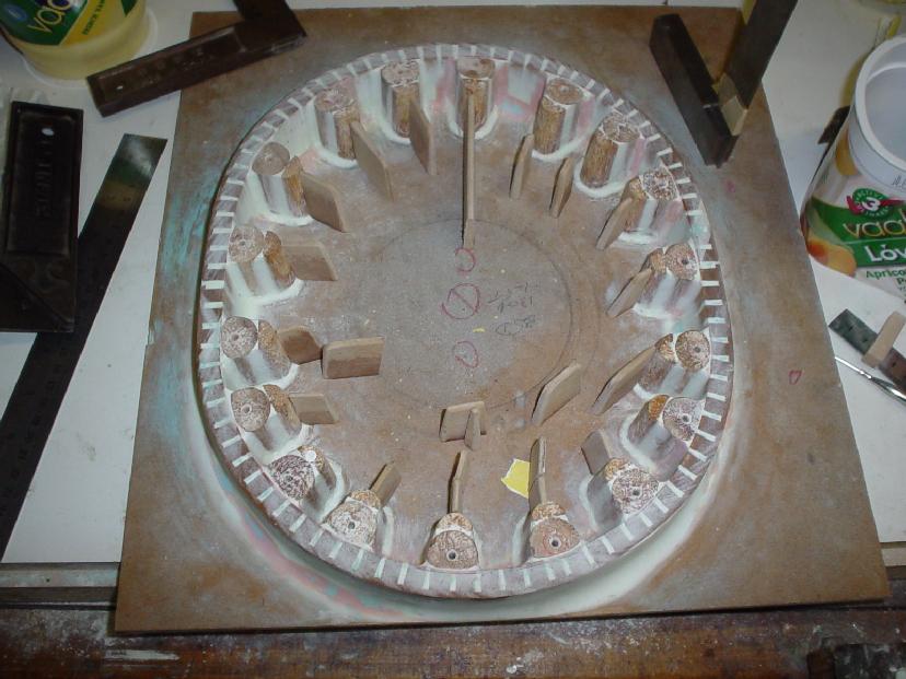
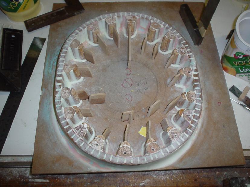
 Thanks for the coolant drawing it is timely for me, as I have just started
the pattern on my design (don't ask - top secret) of the aluminium housing
( see attached photo) -I have a couple of questions please!

1. Looking at your water coolant passages drawing there is a passage at 1
O'clock, which is closed-off - why is that so!

2. I must have missed the outcomes of Vance's support experiment, apart from
what you just advised i.e. less than 3 hp that's good!
Is there anything else you can advise on, in regard to flow rates and
pressures at different RPM.
George ( down under)
First I want to commend you for all the pattern work you are doing on such things
as the aircraft engine bell housing and your current project the aluminum end housings.
This will eventually pay off big time in aircraft use of the wankel engine.

I'll answer your questions this way if you don't mind.

Since Mazda and others have a billion man hours into developing the rotary
it is very wise to copy what they do exactly.  They have extensively
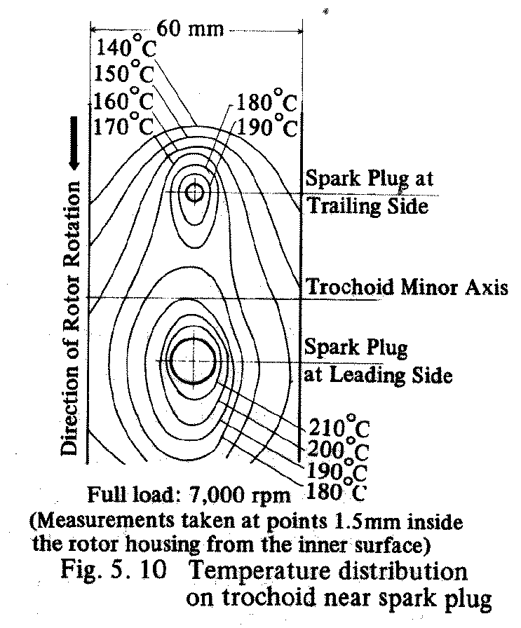
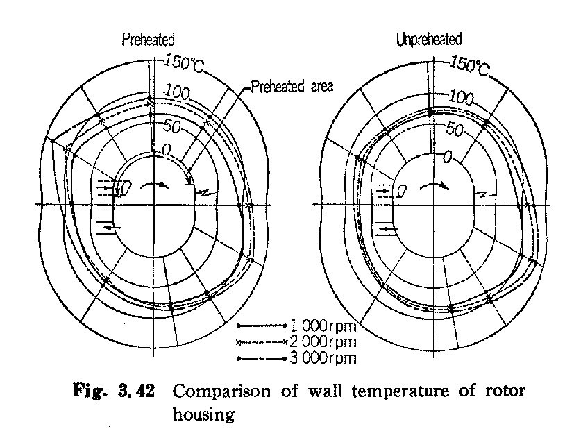
instrumented the engine to measure the temperatures of the metal throughout.
It does not pay to fool with their design.

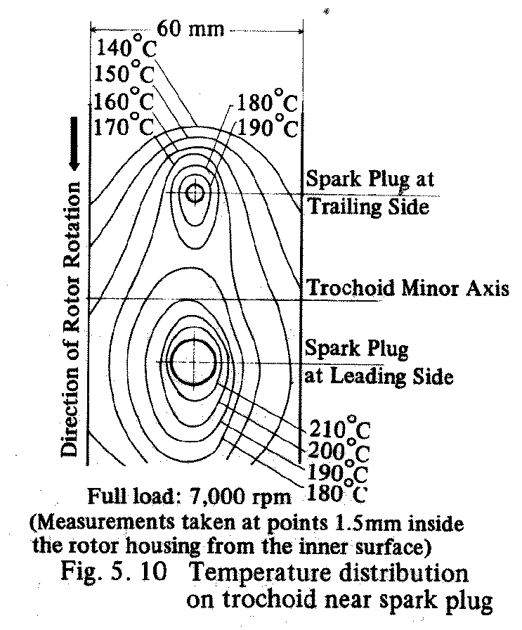
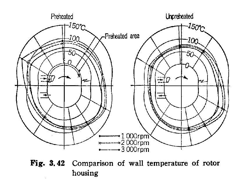
The coolant flow is tailored in an attempt to equalize the temperature of the engine
from side to side while favoring the hot spots around the spark plugs. If this is not
done one side of the wankel tends towards too cool while too hot on the other. When
the metal expands the engine tends to form a banana shape which is not good for
uniform moving part clearances.

Here are some data on these temperature differences. The heat transfer from the
metal to the coolant is dependent on many things but one of the parameters
easily controlled by the engine designer is the flow velocity and volume. Where
the passages are necked down the flow velocity is forced to speed up.
This increases the heat transfer for a given metal surface area. It also
affects the flow rate not only locally but in the entire cooling system.
This makes the design process very complicated.

BTW it amuses me the ignorant arrogance of some people thinking they can second
guess the Mazda engineers on this subject by arbitrarily reducing the
coolant flow as specified by Mazda. They are wasting their time. If anything
the engine needs higher coolant flow when used in heavy duty aircraft applications.
Back when the engine was generating only 130 HP in light duty automotive service
the coolant flow was specified to be 110 to 120 liters per MINUTE!

Paul Lamar

The Rotary Engine NewsLetter.  Powered by Linux.
ACRE NL web site. http://home.earthlink.net/~rotaryeng/
Copyright 1998-2004 All world wide rights reserved.