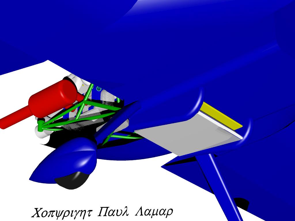
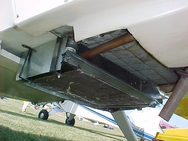
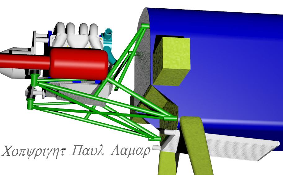
What is wrong with these cooling system
designs?
Paul,
 If the question wasn't rhetorical, there is
no
diffuser prior to the face of the heat
exchanger.
The turbulent entry and "dead" corners will
reduce
the effectiveness of the heat exchanger. Better
would be to angle the heat exchanger and use
the
wedge style feed with a diffuser tapered to meet
the
intake.
Bill Jepson
You also get a B Bill :) To be fair there is
some
subtle factor that just
recently crystal clear to me again. Hint it
affects
air cooled engines as well.

Paul Lamar
Robert LeClercq wrote:
Has no one noticed the frequently discussed worm
drive
hose clamps.
Robert
Good point Robert. Constant torque hose clamps and
silicon rubber hose should be used.
Still not what I had in mind.

Paul Lamar
-Robert LeClercq wrote:
Two of these designs are of very low frontal area.
Your recommended size of 300ci/rotor would imply that
they are also very thick with limited air flow.
Robert-
True enough and that is one of the major drawbacks to this arrangement.
Still not what I had in mind.

Well we are kind of stuck with two inch thick cores under the engine. Thinner would be better.
Most cores will be 20 by 16 inches or 320 cubic inches per inch of rad thickness.
The oil cooler is mounted along side and is about the same length. The oil cooler
is about two inches thick roughly. There fore it looks like we are stuck with two
inch water cores.

Now you could do something like this with thinner  water cores.


Paul Lamar

The Rotary Engine NewsLetter.  Powered by Linux.
ACRE NL web site. http://www.rotaryeng.net
Copyright 1998-2005 All world wide rights reserved.