| Subject: 35 MPG RX8 |
| From: ACRE |
| Date: 4/27/2005, 7:53 AM |
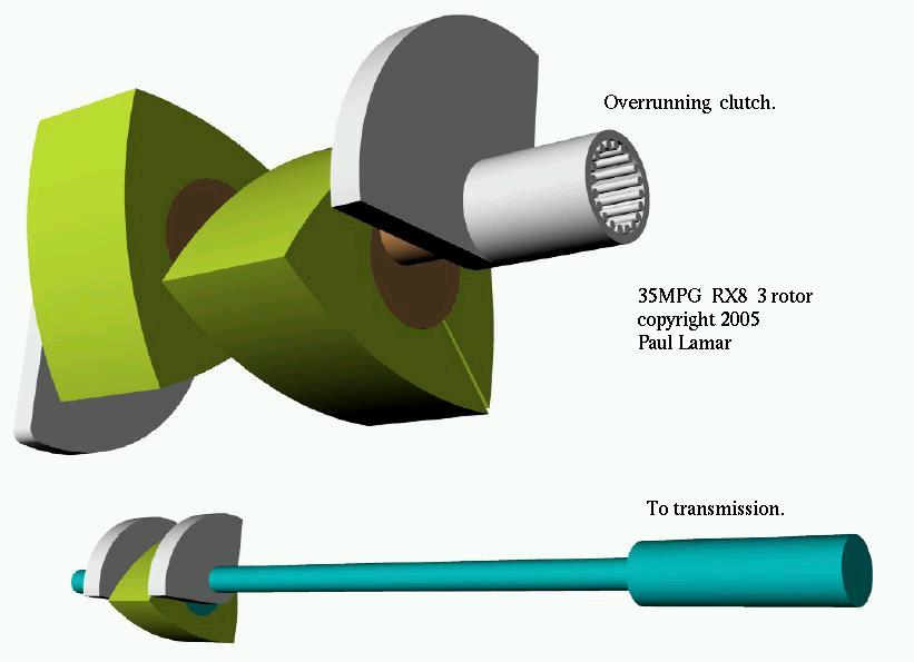
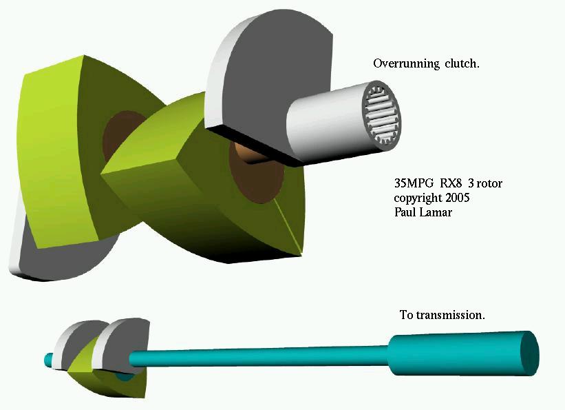
Right now the RX8 engine is running at about 3250 RPM at 65 MPHandgetting 25 MPG. My guess it is using about 30 HP to go 65 MPH. That would be a fuel burn of around 2.6 gallons an hour or 15.6 pounds per hour or a BSFC of around .52. BSFC is defined as the number of pounds of fuel burned for every HP generated in one hour. An RX8 engine running at the best BSFC point should be around.47according to the measurements some have made in aircraftservice.This is a problem in common with all cars. The best BSFC point for the engine is rarely at highway speeds or highwayRPMs.The main reason smaller engines get better MPG on the highway is the small engines are running in a higher efficiency levels. Namely wider throttle openings. Putting smaller engines in cars with higher axle ratios (lower engine RPM) to improve the MPG is called down sizing and down speeding. So a smaller rotary engine would get better MPG in an RX8 car at steady speeds of around 65MPH.A turbo compound rotary could achieve a BSFC of about .38. Turbo compound engines use small turbines extracting HP from the 50% waste energy in a gallon of gas and feeding it back into the output shaft. A well known technology from the 1950's used in airliner piston engines. One of the problems with these A/Cengineswas the failure of an exhaust valve would take out the turbine. Needless to say the rotary has no exhaust valves. The 8 HPturbinewould be geared down by at least ten to one. Working backwards a BSFC of .38 would be a fuel burn for 30 HPof11.4 pounds per hour or 1.9 gallons per hour or a MPG of 34.2 MPG at 65 MPH. The trouble with turbo compounding a 240 peak HP engine while running at 30 HP is it does not appear to work. What we need is a small rotary running at 80% of peak power or more to achieve a BSFC of .38 with a turbo compound configuration. One of the unique features of a wankel engine is the possibility of drilling a straight hole through the output shaft from end toend.If we design a small single rotor turbo compound engine ofaround50 HP we can achieve 35 MPG on the highway at a steady speed of65MPH. Thisengine could feed its power through the large two rotor engineshaft while thetwo rotor engine is shut down. The large engine is only neededforaccelerationand climbing hills. All accessories such as water pump andalternator wouldbe driven by the small engine. Here is a 3D of such a configuration. Comments are solicited. This is going on the web site soon. Paul LamarReally good idea! I was wondering..... Could one use a 3 rotor, the third rotormodifiedto act as the turbo compound? The compression side of the #3rotorhousing plumbed to the exhaust of rotors 1 & 2, timed so theexhaustpulse powers the 3rd rotor. Maybe the timing of the rotors is not conducive to this and youwouldneed a custom e-shaft. Weight wise it's probably not as appealingeither.Just thinking....always thinking... Chris CosmanWhat you want to do is stop the not needed rotors as they consume friction HP. Paul LamarMark R Steitle wrote:Paul, Couldn't you accomplish this by "selective decoupling" of the third rotor? Maybe a spraig clutch could be made to work. The 20Be-shaftisalready split. Mark S.That could be tricky as there is little room in the engine for that. Also a stock size one rotor would still be too large for road load. What you would need is something about half the size of the stock one rotor. Paul Lamar Paul, Let me try again and see if I can explain my concept a little clearer. The three rotor e-shaft connects rotors 2 & 3 pretty much like a 13b does, except for the "snout" sticking out the front end that couplesthe#1 rotor to the rear two rotors. The two piece shaft uses a keywayandfriction to lock them together. If you left out the keyway, added a plain bearing or two, drilled the main e-shaft to accept athrough-shaft(as you described) you could then put a clutching mechanism on thefrontside out near the oil pump and drive back through the engine and into the transmission. The #1 rotor could be a smaller displacement as it would have to be individually balanced anyway. Mark S. (going back to lurking)How about a sketch? :) I think I understand what you are saying. Paul Lamar
Paul,
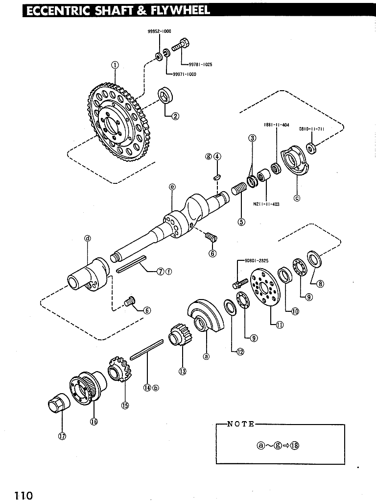
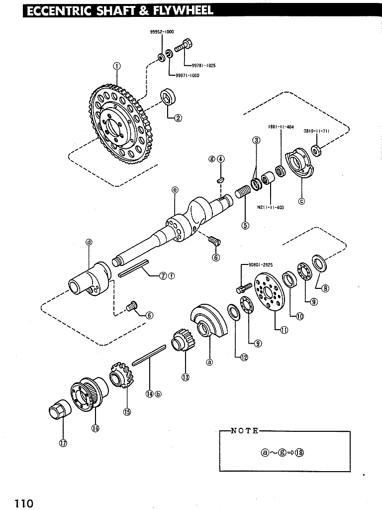
Sorry, but I don't have CAD capabilities on my work computer.  The best
I can do for now is this exploded view of the 20b e-shaft.  The small #1
rotor e-shaft would need bearings to allow it to spin freely on the main
e-shaft while operating in economy mode (#1 rotor only).  It already has
a front bearing, so one additional bearing is all that would be needed.
As in your concept, it would need a way to couple the #1 rotor e-shaft
to the transmission by boring through the main e-shaft and using an
inner shaft, similar to how it was done with the Corvair.  A small
coupling/counter-weight would connect the inner shaft with the #1
e-shaft.  Power from #2 & 3 rotors would be through the rear as before.

If you handled the coupling/de-coupling in the transmission, you
wouldn't need a spraig clutch on the engine.

If you kept all rotor dimensions the same and only reduced the rotor
width, you could still use 20b/13b side housings.  It would require a
special side housing (or adapter plate) if you're using a scaled-down
rotor.

This would make a great engine for a luxury euro-coupe.

Mark S.
I think my way is cheaper and simpler as the power from the front rotor does
not have to go forward first and then back. The clutch is always connected
to the front (small) rotor. This beats the current Daimler/Chrysler 4-6-8 engine as the
deactivated pistons don't have to go along for a free ride. Less overall
engine friction.

BTW I also think the current 13B and RX8 rotors are not wide enough yet.
I think one would get a better combustion chamber shape with wider rotors
like the Diamond/Midwest rotary engine has. A square based combustion chamber
has a better surface to volume ratio than a rectangular based shape.

Paul Lamar


The Rotary Engine NewsLetter.  Powered by Linux.
ACRE NL web site. http://www.rotaryeng.net
Copyright 1998-2005 All world wide rights reserved.