> >
> > Rotary Engine wrote:
> >
> > > I updated the intake manifold section showing the home made
> > > p-port and low cost sheet metal slide throttle with Teflon
> > > slide.
> > >
> > > Paul Lamar
> Paul
>
> On the manifold mounting flange at the rear end, what is the slotted
area
> for? Also you didn't answer my question previously that being, what
happens
> to the disused side ports, are they just covered up by the mounting
flange
> or do you propose to fill them?
>
> Tony Beaton
>
> I don't follow you. There is no mounting flange.
> First I assume you are talking about the P-port engine.
> all disused side ports are filled with high temp epoxy. JP Weld can be
used
> if you first heat the containers in boiling water to thin it out and
then
mix it.
>
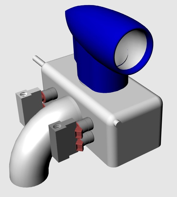
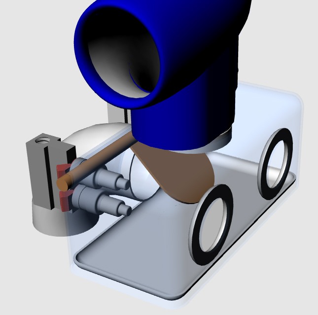
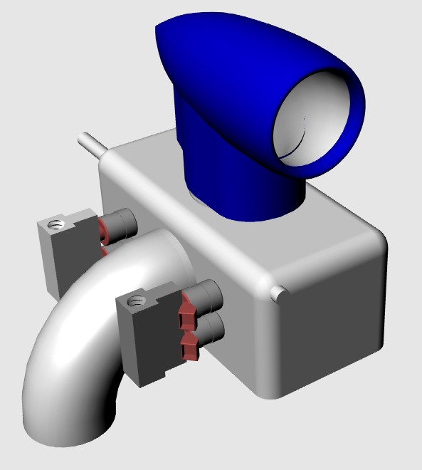
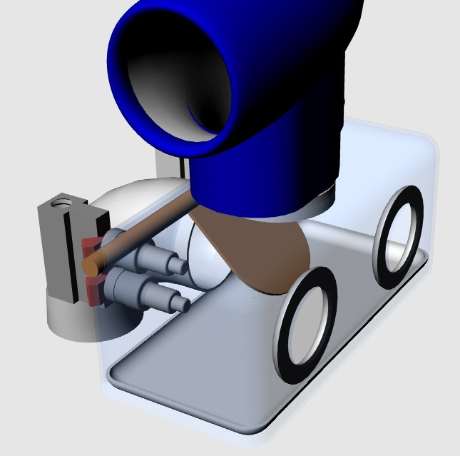
> If it is the slot in the slide throttle then that is to accommodate the
> throttle clevis that connects with the push pull rod going to the
instrument
> panel. Here are a few pics & 3D illustrations that hopefully will clear
things
> up.
>
>
> Paul Lamar
Paul
These pictures are very interesting.
Do you have a dimensional sketch of the sleeve and it's flange and
mounting?
I am guessing that the sleeve is pressed in, how is the flange attached;
press fit, welded or glued?
Do you have a dimensional sketch of the slide Teflon throttle?
Will you need to have a heat shield between the muffler and the Teflon?
A question on theory, should not the throttle be upstream from the
injectors
in the clean dry air, otherwise It could be subject to gummy buildup from
the wet air/fuel mixture?
Tony Beaton
The sleeve is glued in with high temp epoxy. JP Weld will work if
first heated before mixing to lower the pourabilty. Flanges
are tig welded to the tubes. Hundreds of P-port engines have
been built this way for the last 30 years.
Yes on the heat shield.
The throttle is where it is because the P-port rotary does not idle
well if the throttle is upstream. The intake runners store
exhaust gas due to valve overlap causing erratic firing at idle.
No problem with deposits so far.
We have an NC hole punch and a computer program to punch the holes in
flanges and front and back plates. This brings the cost way
down.
Paul Lamar
Paul
Your closing comments lead me to ask, are you producing these sub assemblies
or parts for sale ie;
Sleeve and flange weldment.
Throttle or plates to make one.
The runner 'U' pipes.
What about the air box or are you going to give us a sketch to go by?
How long is the insert sleeve, what is the wall thickness (I assume 2" O.D.
6061 )
Do you have a machining sketch yet for the rotor housing or do we just bore
it 2" diam and leave a lip with an inner bore of 1-7/8", centered on the
side casting cross hatch?
Now more food for thought, I hear what you're saying about the idle, but as
to the point of the valve overlap and exhaust gases the Rx8 write up says
that Mazda has illiminated this in the Renesis, (see
http://www.rx8.co.nz/Rotary/renesis.aspx ). Is it because of a flat sided
piston with no dish, can what they have done be adopted here, then couldn't
the injector block be attached to the top of the insert sleeve with the rail
running inside the 'U' so as to reduce the overall height in the cowl?
Tony Beaton
Yes. We are working on setting up a distributor
No drawing yet on boring the rotor housings.
Sleeve is 6061 T6 2' OD .065 wall.
Lots of ideas on the air box. This is the most sophisticated however
it is highly application sensitive. Uses a Zero Manufacturing company
deep drawn aluminum box.
Paul Lamar.
The Rotary Engine NewsLetter. Powered by Linux.
ACRE NL web site.
http://www.rotaryeng.net
Copyright 1998-2005 All world wide rights reserved.