Hi, all....just wanted to share the results of my recent experiment.
Dan
Cruger recently suggesting adding VG's in front of the NACA duct, as
did
several other canard builders on another list. I decided to try it, and
here are the results.
I put a second pitot tube in my Cozy NACA scoop hooked up to a second
airspeed indicator. I found that without the VGs, the scoop ASI would
fluctuate quickly to zero and back, and the scoop speed was about 30-35 kts
lower than regular pitot speed. With two large VGs mounted ahead of the
scoop (similar to the pictures sent), the fluctuations almost stopped
altogether and the difference in speeds was only about 18 kts.
So . . . without the VGs it appears that a lot of air skips over the
scoop. My guess is that the VGs induce vortices that energize the boundary
layer on the belly of the airplane which helps the boundary-layer air follow
the contour of the NACA and the inward rotation of the vortices assists the
air to enter the scoop.
I now have four smaller VGs mounted adjacent to the forward sides of the
NACA. Can't say they're better or worse than two larger ones mounted ahead,
but they all helped the CHTs.
BTW, the rapid flux trashed my second ASI. Use a manometer or some sort
of restriction in the line if you do a test like that.
--Kent
Cozy IV - 230 hours
Good work Kent. Keep it up. Please get a chunk of kitchen foam and hot
glue it to the end of a few tubes and measure some pressures for me on both
sides of the engine. The back side is as important as the front
side, It is the pressure differnece between them that matters.
Perry Mick can confirm that.
The NACA scoop is designed to generrate vortices.
That how it works. When it does work :)
Here is a list of references on Submerged inlets free for downloading
from the NACA web site.
http://naca.larc.nasa.gov/index.cgi?method=simple
Paul Lamar
--
The Rotary Engine NewsLetter. Powered by Linux.
ACRE NL web site.
http://www.rotaryeng.net
Copyright 1998-2005 All world wide rights reserved.
searching for "Submerged Duct" 	displaying records 1 - 6 of a total of 6
1. 	An experimental investigation of the design variables for NACA
Emmet A. Mossman , Lauros M. Randall , NACA Ames Aeronautical Laboratory
(Moffett Field, Ca, United States)
NACA RM-A7I30, , 1948
Information concerning the parameters and design variables affecting an NACA
submerged duct design is presented. The principal variables investigated
include entrance width-to-depth ratio, ramp-wall divergence, ramp angle, and
deflector size. Tests were also made to show the effect of variation of
boundary-layer thickness and ramp-floor contour. Pressure recovery at the
duct entrance and after slight diffusion, pressure distribution over the lip
and ramp, and drag are given as functions of the inlet velocity ratio of the
entrance. An evaluation of the NACA submerged entries indicates that
satisfactory duct characteristics may be found for a range of the test
variables. It appears that an optimum NACA submerged inlet design should
employ curved diverging ramp walls, a 5 degree to 7 degree ramp angle, and a
width-to-depth ratio of from 3 to 5. The boundary-layer thickness of the
surface into which the inlet is placed was found to have a large effect on
the pressure recovery. Possible applications of this types of inlet and
their particular advantages are discussed.
http://naca.larc.nasa.gov/reports/1948/naca-rm-a7i30/
Updated/Added to NTRS: 2003-08-19
2. 	An investigation of submerged air inlets on a 1/4-scale model of a
typical fighter-type airplane
Delany, Noel K. , Ames Aeronautical Laboratory, Moffett Field, Calif.
NACA Research Memorandum A8A20, 48 pp. , 1948
Wind-tunnel tests were made of submerged air inlets on the fuselage of a
1/4-scale model of a typical fighter-type airplane. The results are
presented for ramp plan forms with parallel and diverging walls, and show
the effects on the ram recovery ratio and predicted critical Mach number of
the duct entrance location (forward of the wing and over the wing), internal
ducting efficiency, angle of attack, and the use of deflectors. Drag
increments of the inlets are presented for the forward location.
http://naca.larc.nasa.gov/reports/1948/naca-rm-a8a20/
Updated/Added to NTRS: 2003-08-19
3. 	Tests of submerged duct installation on a modified airplane in the
Ames 40- by 80-foot wind tunnel
Martin, Norman J , NACA Ames Aeronautical Laboratory (Moffett Field, Calif.,
United States)
NACA RM-A7I29, 25 pp. , 1947
No Abstract Available
http://naca.larc.nasa.gov/reports/1947/naca-rm-a7i29/
Updated/Added to NTRS: 2003-08-19
4. 	Development of NACA submerged inlets and a comparison with wing
leading-edge inlets for a 1/4-scale model of a fighter airplane
Mossman, Emmet A. , Gault, Donald E. , Ames Aeronautical Laboratory, Moffett
Field, Calif.
NACA Research Memorandum A7A31, 44 pp. , 1947
Characteristics of NACA submerged duct entries and wing leading-edge inlets
designed for a 1/4 scale flow model of a fighter-type airplane powered by a
jet engine in the fuselage are presented.
http://naca.larc.nasa.gov/reports/1947/naca-rm-a7a31/
Updated/Added to NTRS: 2003-08-19
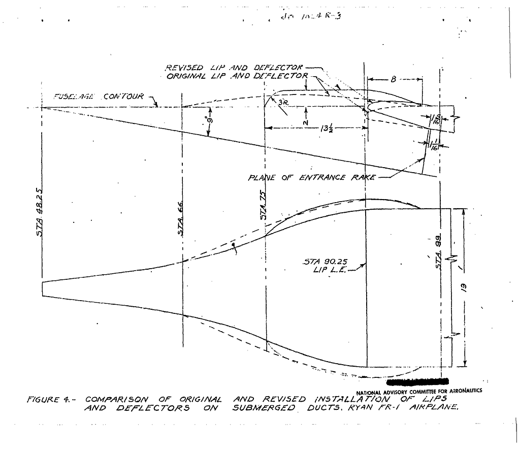
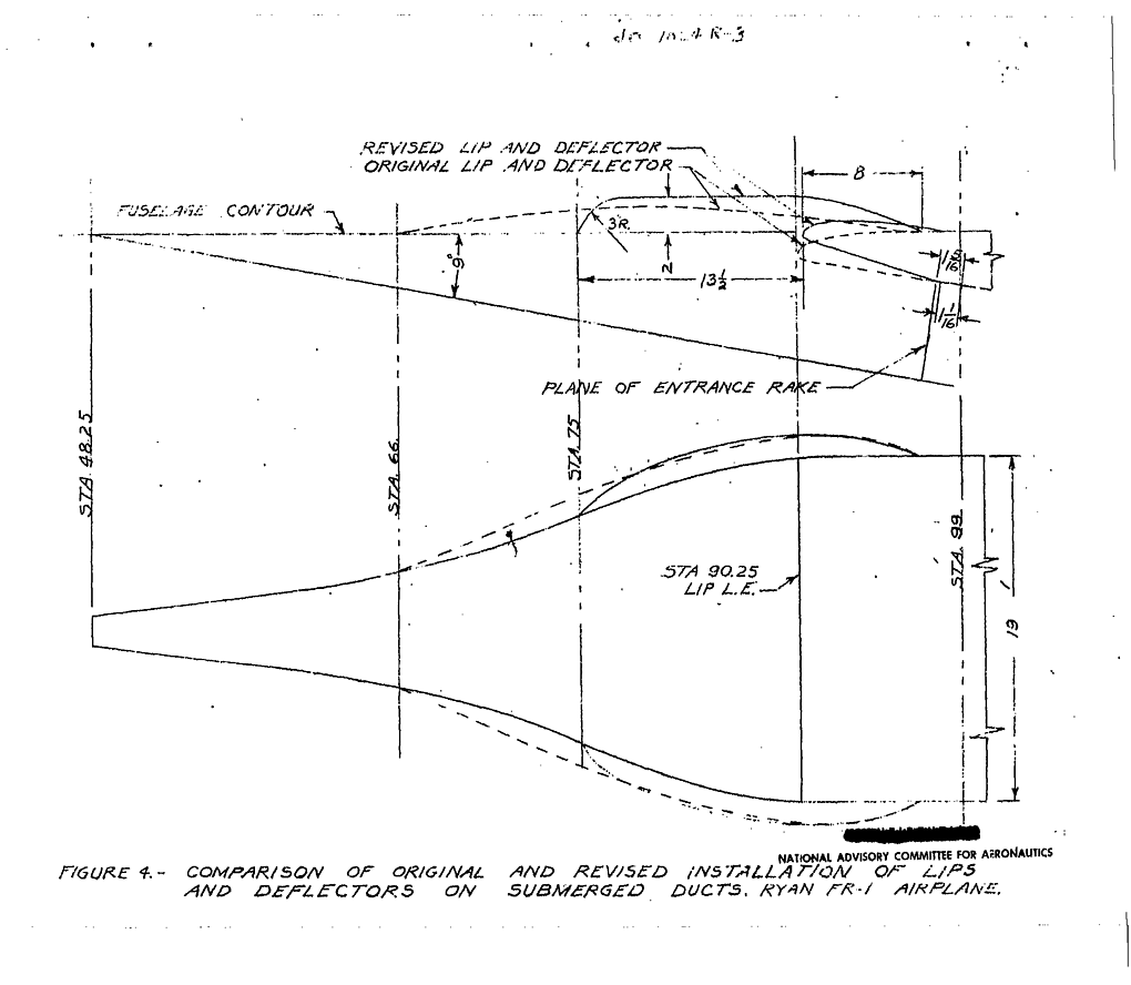
5. 	Tests of submerged duct installation on the Ryan FR-1 airplane in
the Ames 40- by 80-foot wind tunnel /y Norman J. Martin
Martin, Norman J. , Ames Aeronautical Lab., Moffett Field, CA
NACA Research Memorandum A7D14, 27 pp. , 1947
An investigation of an NACA submerged intake installation on the Ryan FR-1
was conducted to determine the full-scale aerodynamic characteristics of
this installation. In addition, tests were conducted on the submerged inlet
with revised entrance lips and deflectors to determine the configuration
which would result in the best dynamic pressure recovery measured at the
inlet for this installation without a major rework of the entrance. Stalling
of the air flow over the inner lip surface created excessive dynamic
pressure losses with the original entrance. The revised entrance produced a
12-percent increase in dynamic pressure recovery at the design high-speed
inlet-velocity ratio and resulted in an improvement of the critical-speed
characteristics of the entrance lip. A complete redesign of the entrance
including a decrease in ramp angle and adjustment of lip camber is necessary
to secure optimum results from this submerged duct installation.
http://naca.larc.nasa.gov/reports/1947/naca-rm-a7d14/
Updated/Added to NTRS: 2003-08-19
6. 	An Experimental Investigation of NACA Submerged-Duct Entrances
Charles W. Frick , Wallace F. Davis , Lauros M. Randall , Emmet A. Mossman ,
Ames Aeronautical Laboratory, Moffett Field, CA
NACA ACR-5I20, , 1945
The results of a preliminary investigation of submerged-duct entrances are
presented. It is shown that an entrance of this type posses desirable
critical speed and pressure recovery characteristics when used on a fuselage
or nacelle in a region of low incremental velocity and thin boundary layer.
The data obtained indicate that submerged entrances are most suitable for
use with internal-flow system which diffuse the air only a small amount: for
example, those used with jet motors which have axial-flow compressors. When
complete diffusion of the air is required, fuselage-nose or wing
leading-edge inlets may prove to be superior. The results of the
investigation have been prepared in such a form as to permit their use by a
designer and the application of these data to a specified design is
discussed.
http://naca.larc.nasa.gov/reports/1945/naca-acr-5i20
Updated/Added to NTRS: 2003-08-19

searching for "Submerged Duct" 	displaying records 1 - 6 of a total of 6

Sponsored by the NASA Scientific and Technical Information Program Office
Responsible NASA Official: Calvin E. Mackey; Curator: ConITS Development
Team
Viewers: Adobe Acrobat (PDF), PostScript, MS Office, Compression
Privacy & Copyright, Ordering NASA Information, NASA STI Help Desk
Last Updated: Mon Apr 12 12:00:00 EDT 2004