If we were really clever we could build an engine simulator
into the plug in PC board we are talking about to break out
Tracy's computer system wiring to better connectors.
For crude injector pulse width display you could use four LED bar
graph arrays. They are getting quite sophisticated now a days.
Crank Angle sensor is a single chip oscillator.
Small pot for changing simulated RPM. Small
3 digit seven segment LED and counter for simulated
RPM indication. Will double as a small tach when
the engine is running.
Thats it. You unplug the vacuum hose from the engine
and plug it into Tracy's pressure sensor.
Pump it to the intake manifold pressure of interest and
program the pulse width at each selected RPM.
Did I miss anything? What do you think... all you EE types
out there?
I would buy one in a heart beat. Could save hours of
tuning time in the air or on the dyno.
Just take notes on what needs to be changed when flying
around or on dyno runs.
This LED bar graph is kind of large at one inch long but smaller
ones are available I am sure. Notice it is end stackable so one
part in 20 (5%) for pulse width is doable with 8 of these.
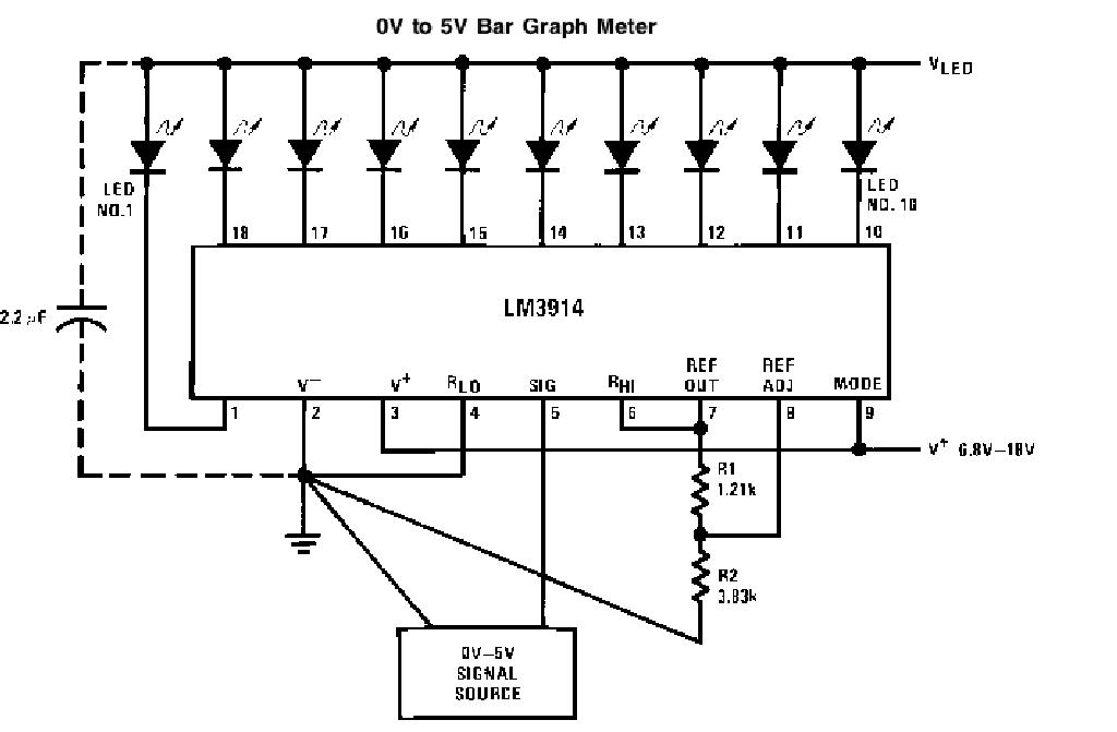
Use one of these LM3914 chips per 10 segment LED bar graph is needed.
the 12 volt negative going injectors pulses can be converted
to a 0 to 5 Volt analog signal by a diode and an integrating capacitor
then fed into this chip.
This simple 555 and very cheap pulse generator chip can serve as
a crank angle simulator. The resistors are replaced by a pot to change
the simulated RPM.
Paul Lamar
The Rotary Engine NewsLetter. Powered by Linux.
ACRE NL web site.
http://www.rotaryeng.net
Copyright 1998-2005 All world wide rights reserved.