Paul,
This is for the rotor heads who would like to consider a p-port engine
but are holding back because they don't have access to the machines that
they think are required to do the job. The attached JPG's show what can
be done with a few simple tools.
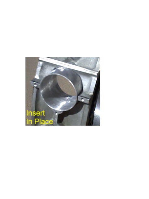
P-Port 1 shows a 2" hole in a rotor housing made with an inexpensive
bimetal hole saw with the housing clamped to the table of a drill press.
Not as accurate and neat as can be done with mill but I believe it's
adequate. The hole is about 0.015" oversize for the 2" OD, 0.049 wall
insert shown. The tube for the insert was expanded for a tighter fit
using an exhaust pipe expander tool (Harbor Freight).
The insert was placed in the hole. Then 4-40 screw hole was drilled and
tapped down through the housing and insert to key the insert position.
The inner contour was scribed on the insert and after a bit of cutting
and filing a very good inside profile was achieved.
The three threaded holes in the housing flanges? around the outside edge
of the insert, P-Port 2 will be used to position, not support, the back
plate of a variable timing slide throttle, copied after yours, for my
single rotor engine.
I have no desire to enter into any discussion of the exact positioning
or size of a p-port. I believe Lynn Hanover when he says they're not all
that critical. My hole was positioned in the center of the hollow above
the exhaust port, angled slightly downward per the LeMans illustration
to avoid the apex lube port. I also believe that a variable timing slide
throttle which will open the top of the port initially will help with
any potential idle problem. Throttle details to follow.
Fred Osborn
--
The Rotary Engine NewsLetter. Powered by Linux.
ACRE NL web site.
http://www.rotaryeng.net
Copyright 1998-2005 All world wide rights reserved.