> I was researching the failure on John Slades EC2 and found some
> disturbing things.
>
> The input power filter uses a choke which is the only single
failure
> point in the EC2. The part was originally specified to be so
over
> rated such that failure could only be caused by physical
damage to
> the part. If an overload occurred sufficient to fail this
part, the
> circuit traces on the board would fail long before the part
would.
> This
> was the rationale for the basic design approach. Don't want
to get
> into
> a discussion of why separate chokes are not used.
>
> At some point the manufacturing facility substituted a
different part
> with same inductance but lower current rating. It was still over
rated
> and sufficient for any foreseeable situation so it was
considered OK.
>
> Still later, the board maker substituted an even lower rated
part
that
> looks almost identical to the previously substituted part. I
was not
> informed of this change. The unit will function normally
with this
> part but it has no extra margin for safety in the event of
mis wire,
> shorted output, etc. I was able to duplicate the failure
John Slade
> had
> by shorting 1 or more ignition driver outputs to ground or
12V input
> power. The original design intent was to allow this
condition without
> failure of the choke.
>
> Point of this message is to announce an AD (airworthiness
directive) to
> inspect and verify the type of choke used on your EC2.
Attached to
> this
> message is a picture of the three types of chokes used. The
left is
> the
> originally specified part. The center part is an acceptable
substitute
> part. The right hand part is the unacceptable choke. If you
have this
> part, do not fly the aircraft until it has been replaced. In
addition
> to the visual difference, you can determine which part by
measuring the
> resistance. The bad part has a resistance over 10 ohms. The
correct
> parts are much lower in resistance.
>
> We will replace the part for you for no charge except shipping
cost as
> specified in the warranty. This is a simple through-hole
soldered
part
> that is relatively easy to replace. If you are qualified to
replace
> the
> part yourself, we will send the correct part at no cost.
>
> Tracy Crook
> Real World Solutions Inc.
Tracy, for the record, I have the original choke. Jerry
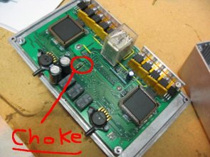
Tracy: Where is this choke located? What do I need to do--do I pull
the cover off? How do I inspect my EC-2? The picture shows which
choke(simply a resistor??) is correct, & which is wrong, but: where do
I look; why measure their resistance if I can visually inspect? If I
measure the resistance, must I disconnect any power source; what about
capacitors; diodes;retained charges; static electricity; etc... please
explain precisely to us non-EEs!
Tomorrow I am doing fast taxi testing; maybe first flight.
John
Andrich
Turbo-rotary Long-EZ
Camarillo, Ca
Sorry, that was an oversight in my near panic to get the word out. Here
is a photo (courtesy of Dave Leonard).
Tracy
--
The Rotary Engine NewsLetter. Powered by Linux.
ACRE NL web site.
http://www.rotaryeng.net
Copyright 1998-2005 All world wide rights reserved.