The ratio of the area's is 2.76 square inches (pipe) over
.007 square inches (leak) or about 400 to one.
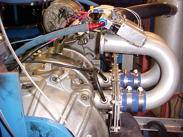
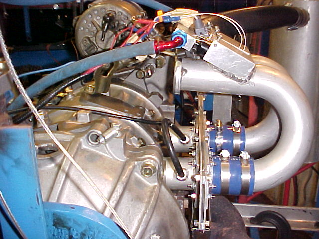
BTW The two vacuum sensor holes, one in each runner, are T'ed
together anyway and they are larger than
.094" inside diameter. Perhaps a thing to try is taping off just one
runner and see if it makes a difference in EGT's, MAP or HP.
There is roughly 400 cubic feet of air per minute going in the
engine at 7500 RPM. Since the inside area of one pipe is .0192 square
foot that is a air velocity in the pipe of 10,416 feet per minute
or 173 feet per second or 118 MPH.
Paul Lamar
Paul,
The sealed version looks much better. I don't believe that the air
leaks are significant at WOT. I would have been more concerned at idle
and part throttle applications. An air leak at idle, (when there is the
strongest vacuum to cause it), can cause very poor idle. There your
ratio of leak to opening is probably more like 10:1. The newer design
will probably idle better.
Now that you have the seal more handled you might consider a labyrinth
seal between the holes. A small series of grooves around the Teflon
block about .030 deep and .010 apart. 6 to 8 grooves would do it. I have
built zero friction air cylinder pistons using such a seal and they work
remarkably well. It might not even be needed after you do the other seals
anyway. FWIW
Bill Jepson
--------------------------------------------------
The main reason to seal the slide throttle is to insure that any
raw fuel finds its way into the engine.
One must remember this is not like a carb. The air pressure sensor
is next to the rotor housing. In theory leaks up stream from
the sensor don't matter. The amount of fuel injected is
only controlled by the air pressure sensor down stream from the
leaks.
The current P-port engine with slide throttle engine will idle
below 1000 RPM at start up. Currently it is so rich it starts
right up from cold (80 F) with no enrichment needed. It will idle
smoothly below 1500 RPM until the plugs foul. Then is must
be run under load for awhile to clear the plugs.
The only real issue is how the instantaneous air pressure is
affected by turbulence or pulses in the runners. Tracy only samples
it once per rev with a high speed pressure sensor. My question is: how
does the air pressure change from millisecond to millisecond?
So far I have been unable to talk Tracy into taking several
samples and averaging them.
This is entirely different than sampling the air pressure once in a
large shoe box type plenum down stream from a throttle body located
at the air intake end of a plenum as he does in his and most other
side port intake systems.
I don't know the answer to this question yet. I need a high speed
pressure sensor data gathering system that will sample the
pressure data at least once every millisecond for at least
as long as it takes to make one revolution of the e-shaft.
Tracy has the basis for such a data gathering system. All it
takes is a serial download port and some EEPROM to store
the samples. And some new software (firmware) of course.
A third question is: how does the minor leak from runner to runner
affect the organ pipe tuning if in fact it does affect it at all?
In this case the main contributor is connecting both runner's pressure
taps together with a hose. See the picture below.
The ideal situation with a p-port would be one pressure sensor
for each runner.
Paul Lamar
The Rotary Engine NewsLetter. Powered by Linux.
ACRE NL web site.
http://www.rotaryeng.net
Copyright 1998-2005 All world wide rights reserved.