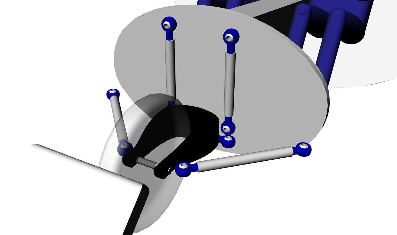
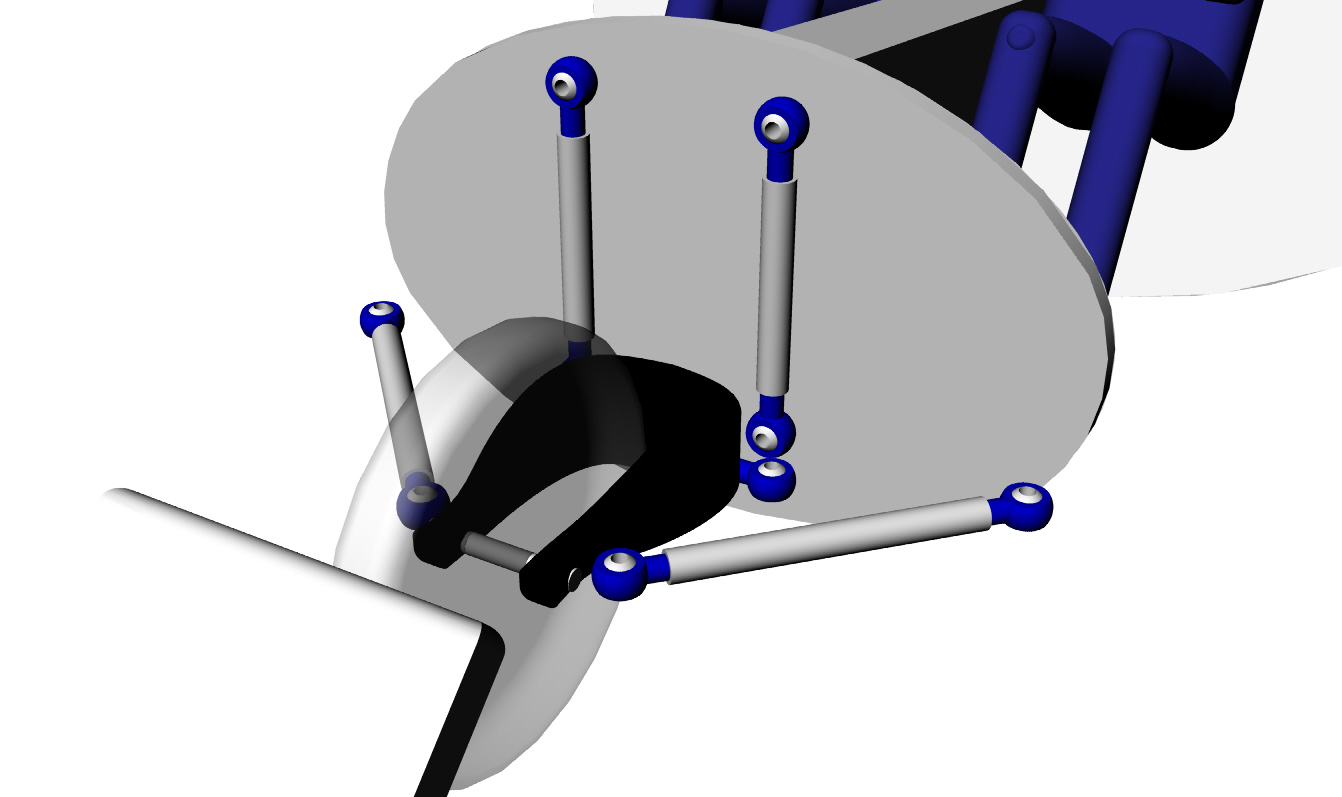
This is my layout for the front suspension.
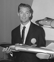
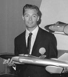
It is based on a design I did for Craig Breedlove's 3 wheel
rocket powered land speed record car 35 years ago. Went 400
mph in the quarter mile using a surplus TRW lunar landing
module rocket motor. Craig was asked how he could possible
steer such a fast car and he said he did not really steer. He
lined it up with the race track and then held the steering wheel
still while the rocket motor fired. The drag runs were quite
spectacular.
When he fired the rocket the car disappeared with
a loud bang in a huge cloud of smoke. The crowd gasped and thought
he blew up in a zillion pieces. If you immediately looked
down the strip you could see the braking parachute open. Needless
to say one or two exhibition runs and the sanctioning body outlawed
the car as being too dangerous for the spectators.
Craig ran it at Bonneville without breaking the record
as he was running out of rocket fuel around 400 MPH. He decided
to remove the wings between the rear wheels and the large laminar flow
wheel pants that I had designed. He did this to save weight.
The car was stable until the rocket motor shut off and then it went into
a Lomchevak at 400 MPH. Needless to say Craig survived because of the
robustly designed cockpit done by Margie Smith. It was two concentric
tubes of .065" thick 7075 T6 riveted to .065" thick 7075 T6 hat sections
every 10 or 15 degrees and was about two feet in diameter. Front and
rear 4130 steel tubing sub frames where torn off.
The car in question here is similar to this picture but it had
no side air intakes of course.
This quote from a web site is inaccurate as the rocket car actually
ran at Bonneville and crashed as I outlined above. That is why you
won't see the actual car in a museum. Just a mock up.
"During the 1970's, Craig campaigned a rocket dragster powered with a lunar module
motor fueled by hydrazine. This led to this consideration of a new rocket-powered
land speed record car, but U.S. government restrictions on the use of rocket engines
and fuels became too stringent to successfully continue the program, and he had to
abandon his rocket car project in the mid-1980s. The full-size, 41 foot mock-up for
that intended rocket car is now exhibited at various museums and is the design
forerunner to his newest Spirit of America land speed record car."
I digress.
Anyway the two down tubes control the camber of the front wheel
as it turns left or right. The pivot axis is a virtual axis formed
at the convergence of the lateral links and the upper convergence
of the down links. Since they are parallel they converge at infinity
in outer space some place so the pivot axis is near vertical.
To add rake angle or caster to the pivot axis you move the top ball
joint in towards each other which makes them converge at a finite
distance above the fuselage. The yoke is made out of half a dozen
layers of carbon fiber. Craig's was made from thick wall square
steel tubing. The link below and in back of the yoke is the
steering link. The steering box and steering arm are not shown.
Nor are the pneumatic cylinders that support the suspension on
the road and retract the front wheel in flight. Nor are the various
required suspension attach brackets shown.
The aluminum links and aluminum ball joints are all stock
sprint car parts. I was at the Ventura dirt track on Saturday night
when my 73 year old friend John Richards was racing his 650 HP sprint
car in the senior's race. Dirt track sprint cars take a lot of abuse.
That is where I got the idea for the light weight suspension links.
Almost all sprint car suspension parts are aluminum and very
reasonably priced because of the volume manufacturing.
The rational for this design is it widely distributes the suspension
loads into the structure unlike a traditional motor cycle fork design.
Therefore it is much lighter than a motor cycle fork arrangement.
Paul Lamar
The Rotary Engine NewsLetter. Powered by Linux.
ACRE NL web site.
http://www.rotaryeng.net
Copyright 1998-2005 All world wide rights reserved.