Hi Paul,
Firstly I will not be going to Oshkosh this year as I have decided to
make the Mustang 2 fly before Christmas. The weeks lost are important to
achieve my goal.
Paul I have carried out many test today and have built many intake ducts
shapes and size to achieve the best result. To achieve a cooling system
that works with a horizontal radiator we need to build the streamline
duct as per the Kays and London dwgs. I have tested many shapes and
sizing today with the end result back to the results from Kays and
London. The wedge shape produces outlet velocity as per the wedge with
the highest value at the small end to almost 0 at the large end. I have
made many ducts and the best is an S that go's through the straight line
of the wedge line. This has given air flow through the core with equal
distribution but a 10% increase over the total area for the same
input.
Paul I will try to do another dwg to enplain this. My numbers do
match the Kays and London but prove the shapes are right. I think the
reason why the numbers don't match is they where done on the Mustang
Spitfire and 109 where the airspeeds and climb rate is different.
Paul I
hope you can follow this. It is hard for me to put all I have found in
words but I will ring you if you think it is needed. In conclusion for
our slower climb out speeds of say 90 knot we need to build the
streamlined diffuser as the conventional diffuser is not good for our
speed range.
Regards Don
---------------------------------------------------------
Sorry to hear you are not coming to OSH.
Well Don I discussed it with Robin and we have decided to visit you, Ian and all
you guys in WA again to see what you guys are up to and perhaps help. Robin loves
to travel anywhere at a moments notice. When is the question. Probably after OSH.
Paul Lamar
What you need Don is an unlimited supply of high speed air. This is best
done with a truck having the cowl and rad located up above the
cab. It takes a big blower indeed and a lot of HP to pump the amount
of air you need to full scale test scoops, ducts and rads.
The truck has a couple of hundred HP. Here is what I did to test
Kays and London type wedge diffusers.
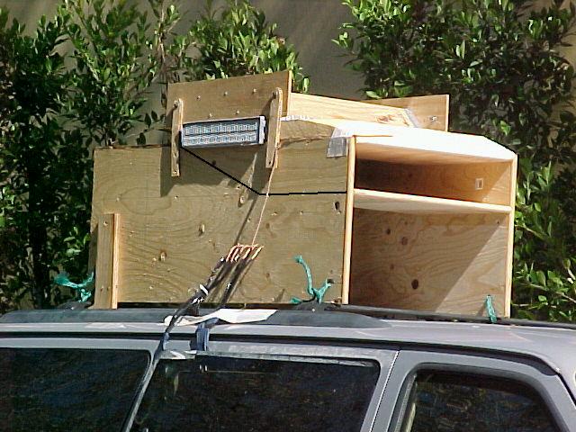
First picture is the Caravan with the test box on top.
the black line on the side of the plywood is the shape of
the K&L wedge shaped diffuser inside the box. Note the copper
tube on the upper left hand corner of the scoop facing forward. This
is the air speed pito tube. Needed if you have any tail or
head winds while testing. This does not measure the air velocity
going into the scoop. That must be done using a pito static
tube inside the scoop. I did not do that as it was of academic
interest only. I would not be surprised if the velocity of the
air going IN the scoop was less than the forward speed of the
truck. What air could or would not go in the scoop bypasses the
scoop and is called external diffusion.
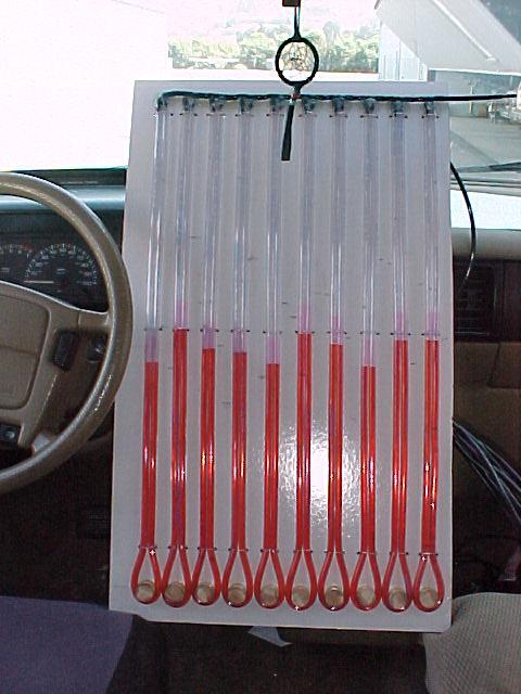
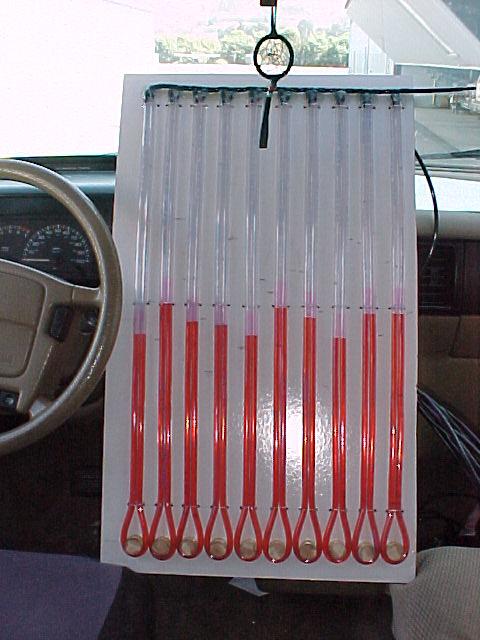
Second picture is the water manometer inside the truck cab.
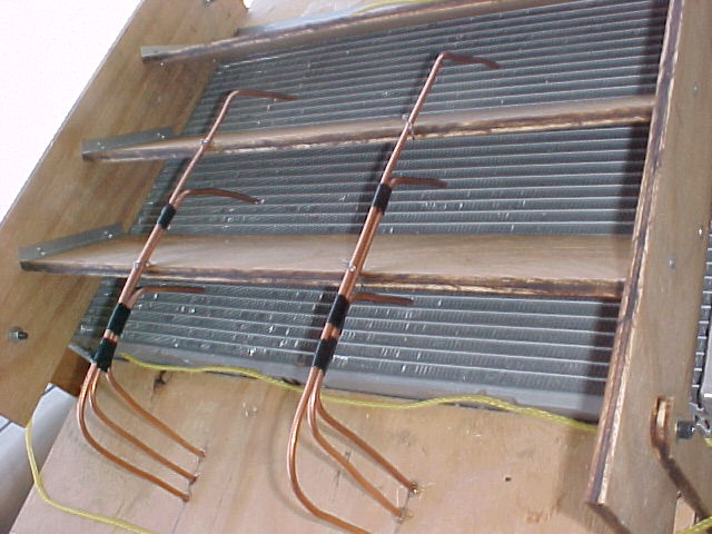
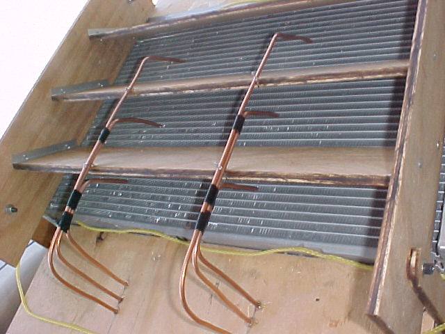
Third picture is the array of pito tubes measuring the
air velocity out of the back side of the rad. If you wish
you can do this using your anemometer.
I got a pretty good uniform distribution of air velocity coming out
of the back side of the rad using this test set up.
More pics soon.
Paul
The Rotary Engine NewsLetter. Powered by Linux.
ACRE NL web site.
http://www.rotaryeng.net
Copyright 1998-2005 All world wide rights reserved.