Paul,
I shipped your injector test-bench today. Couple of notes on how to set
up & use:
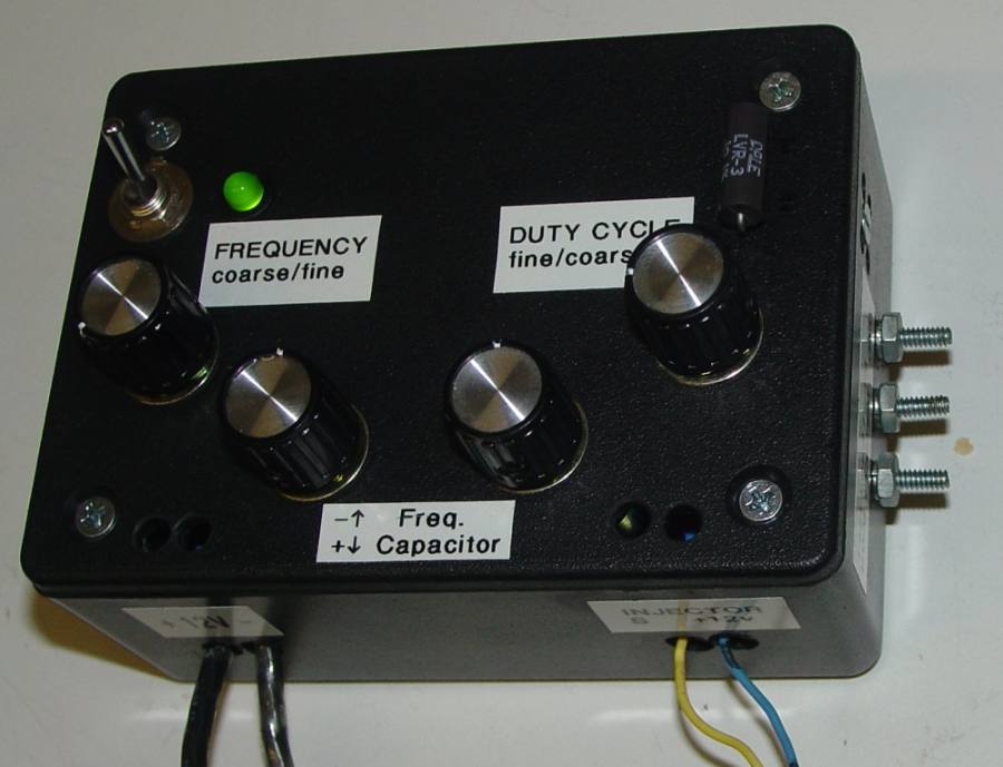
- The testbench has an adjustable frequency range with coarse & fine
adjustment knobs.
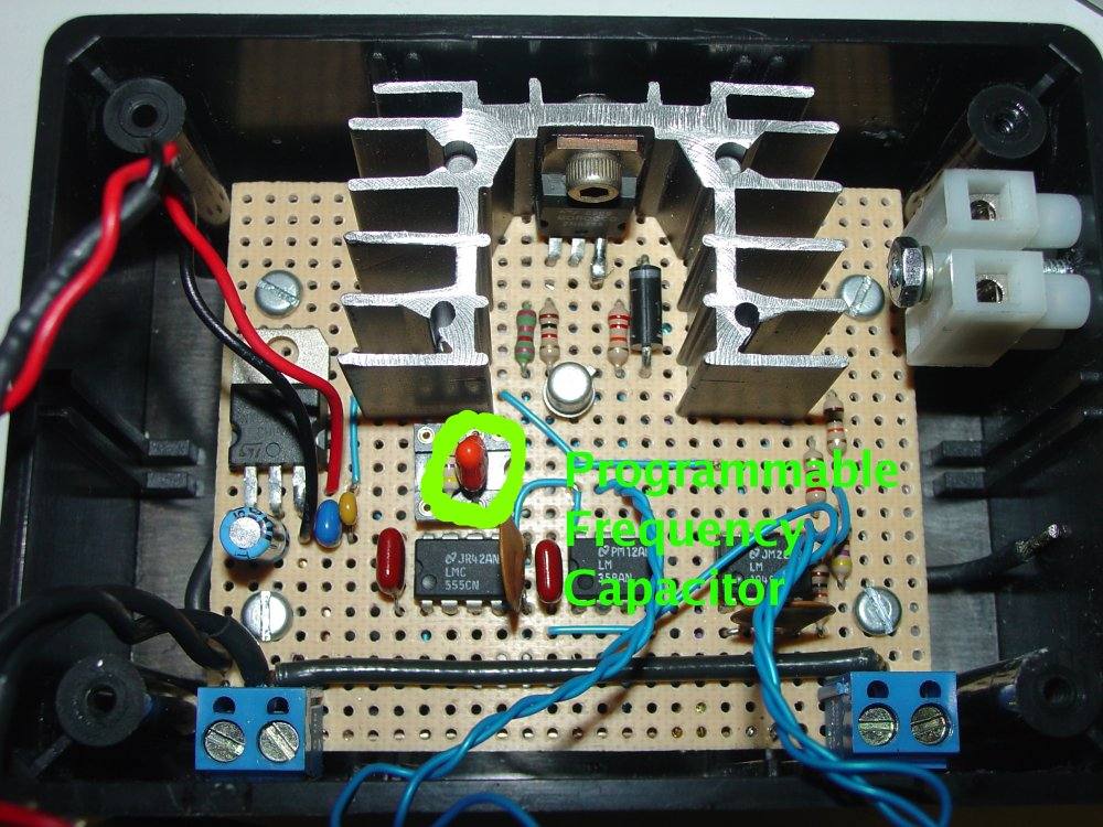
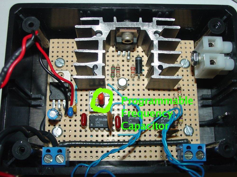
- This hardware has a programmable frequency range, set by an
interhangeable capacitor (first pic.). The one in there should get you
~600RPM to ~8500RPM. I included an extra cap that enables ~1/10th of
the speed range. You can experiment with similar values if you wish.
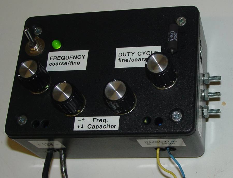
Just observe the polarity as shown on the top cover.
- The PWM has a true 0-100% duty cycle with coarse and fine
adjustments.
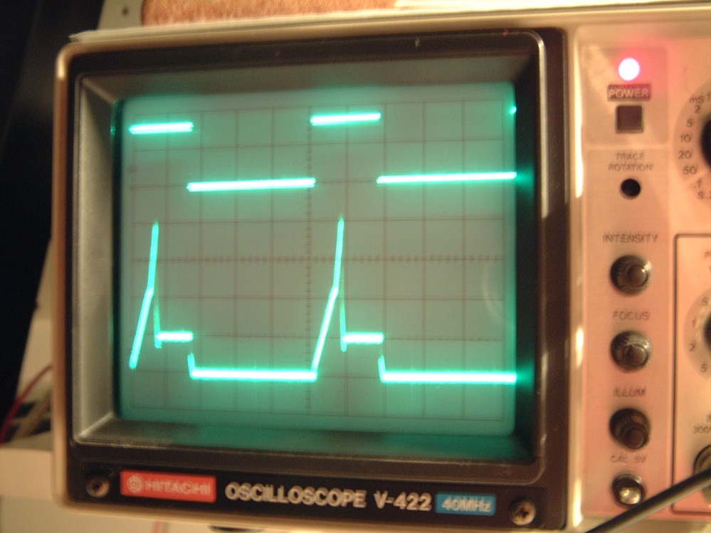
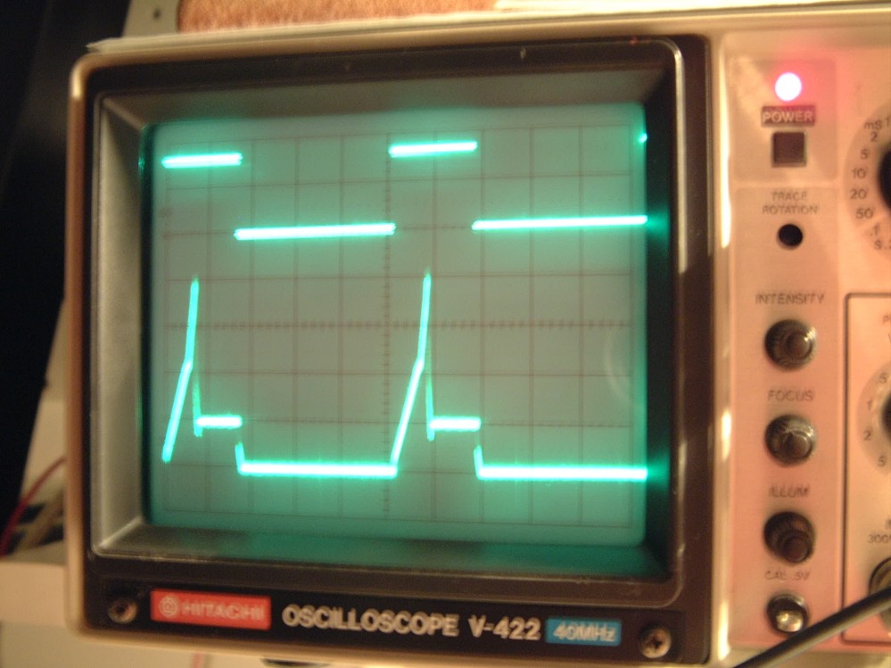
- There are three external test leads for an oscilloscope or digital
timer so you can monitor the injector current and the PWM signal. (last
pic).
- The resistor in the second picture (top right of case) is used for
setting the peak/hold current. I included extra resistors.
- Peak current: Rs = (0.4V drop across Rs)/(peak injector current
desired) For a 6 amp injector, select a 0.67ohm resistor (round to 0.7
for even value).
- For saturation type injectors, there is no need to calculate the Rs.
Just leave it at 0.1 ohms or similar values and the driver circuit
should not transition to the hold current state.
This configuration is not a switched hold current circuit (safer RF
levels around other sensitive electronics), therefore the transistor can
get warm depending on the holding duty cycle.
A side benefit is that you can use the PWM output for other projects.
Just keep in mind you will need to use a transistor/optocoupler to
convert this 3.6V signal to other logic levels. I will post a schematic
if others are interested in building their own.
Enjoy,
Marc Pedings
Thanks Marc. Looking forward to demystifying some of these injectors.
Paul Lamar
--
The Rotary Engine NewsLetter. Powered by Linux.
ACRE NL web site.
http://www.rotaryeng.net
Copyright 1998-2005 All world wide rights reserved.