> Even after looking at the picture, I still don't understand the
problem with averaging.. Maybe you could describe the issue in a
different way.
>
>
> Thanks,
>
> Matt-
>
> No problem Matt.
>
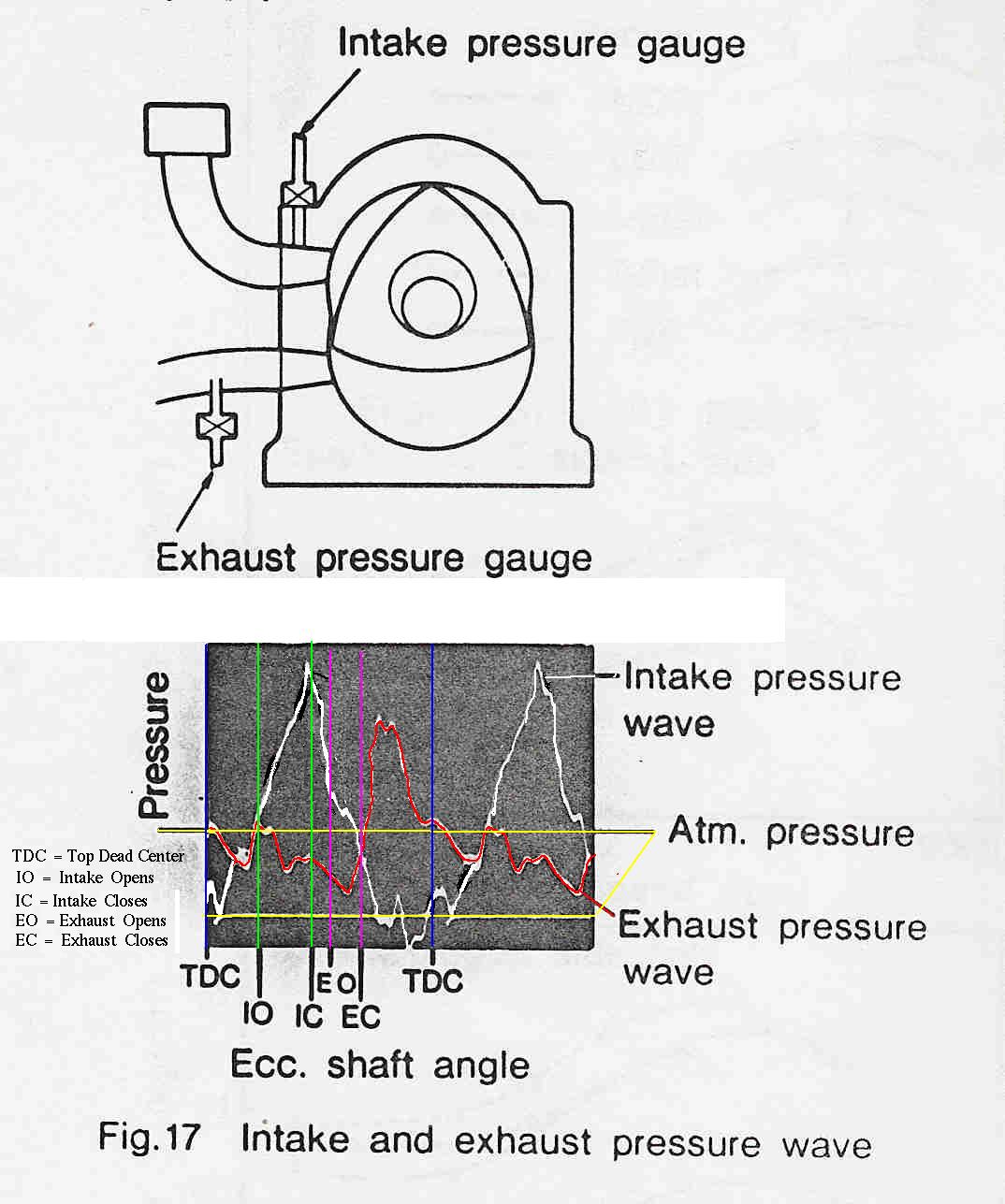
> Think of these curves as the side view of some mountains
> and valleys. Averaging would be like drawing a straight line half
way up the intake mountains... valleys included. What you might get
is just atmospheric or static pressure (top yellow line) as the
valleys below the top yellow line are below atmospheric pressure and
those above are above atmospheric pressure. What you want is
atmospheric pressure PLUS the area of the side view of the
mountain between to the two green lines and above the top yellow
line. Namely the additional air going into the engine
> when the port is open due to the dynamic ram effect. The mass of air
going into the engine is directly proportional to the side view area
of the mountain above the top yellow line PLUS the top yellow line.
>
> Tracy refers to this as total pressure. This represents the 20% of
additional air you get with a highly tuned intake. This is also why
the volumetric efficiency of a p-port tuned intake rotary engine is
roughly 120%. This is also probably why we are 20% lean on the top
end.
>
> BTW Chrysler referred to the effect years ago as RAM charging and
the roots of the name are still used by Daimler/Chrysler.
>
> I hope this clears it up. Perhaps someone else can give it a try as
well. Never hurts to have someone else explain things in different
words.
>
> Paul Lamar
snip
Hi Paul,
Okay... I think I finally get it.. Your point: The problem is that as
the volumetric efficiency of the engine relatively improves as RPM
reaches the P-port tuning peak value, causing the average value of the
manifold pressure to fall [?? rise] - the engine is effectively taking
deeper breaths, so
increased average vacuum [not vacuum], even WOT.. The lowered averaged
manifold
pressure (lower MAP reading) causes the computer to erroneously lean the
mixture. Is that what you are saying?
I still think this effect can be tuned out effectively (and more simply)
- the fuel delivery curve should end up reflecting the increase in
volumetric efficiency associated with changes in RPM.
And, I still think that the problem you encountered was more likely
caused by the FI computer taking a quick snapshot of the MAP at the
wrong time - at a time when the MAP value was really low. I think you
already said this.. We just disagree on how to fix it.
Regards,
Matt-
VE N34RD, C150 N714BK
------------------------------------------------------------
Not exactly. Think of things in absolute pressure terms. We are walking
around in 15 psi pressure at sea level. That is 30 inches of mercury
using a manifold pressure gage. Our body would be crushed if it were not
for the same pressure being in our lungs.
Now what happens in the intake manifold due to an organ pipe tuning
effect is the PEAK pressure pulse may go up to 200% of
15 psi or 30 psi (60 inches of Hg). 100% more than wide open throttle.
When the port is closed at the RPM tuning point the pressure also goes
below 15 psi (30 inches of Hg) for awhile. Perhaps all the way to zero
pressure. The average is still 15 psi (30 inches of Hg). Remember the
throttle is still wide open. The key word is "PEAK". What we are
interested in is the amount or mass of air that flows into the engine.
That is proportional to the area under the peak plus the
the air flowing into the engine due to atmospheric pressure alone.
If the shape of the pulse were a right triangle the area would
be 1/2 base times height or 7.5 psi so to speak. That would
be 50 percent more air or the equivalent to 22.5 psi (45 inches of Hg).
In the real world we don't really see that much air. What we see is
about 20% more or the equivalent to 18 psi (36 inches of of Hg).
Using the term vacuum confuses the issue. A pure vacuum is just the
absence of pressure and what one would get in outer space.
BTW pressure at sea level expressed in psi is merely the weight of a
long, one by one inch, column of air up to the start of space
expressed in pounds. In other words the column weighs 15 pounds.
I don't mean to be condescending here I just don't know the level of
Physics education of every one on here. I am trying to explain things
from the most basic level possible.
I DO NOT disagree with you on merely changing the map table entry to
correct for this effect. It would be better however if we did not have
to do that 128 times. One for each .12 psi increment in the intake
manifold pressure. It would be better if the computer would
set the mixture on the basis of the actual mass of air entering
the engine at any RPM. That is exactly what a mass air flow sensor does
in an automotive EFI system or a carburetor does for that matter.
I think Tracy could do it by taking five or ten equally spaced pressure
samples during the time the port is actually open and integrating them.
Then add or subtract that number from the atmospheric pressure in the
intake manifold. The computer is fast enough to do this no problem. It
can probably get a sample in a few millionths of a second since it runs
at 33 million instructions per second more or less. I am sure it is now
twiddly its thumbs most of the time.
To Tracy credit there is an auto tuning mode where the
computer looks at the O2 mixture monitor installed in the exhaust
pipe and adjust the MAP table entries accordingly. I have not tried that
yet. That might solve the problem. I can see a scenario when
descending where that might not work. If it were me I would
also look at the EGT to get a better feel for what the
engine was doing.
Paul Lamar
Wish I had time to discuss this at length but alas, I don't. Working
on other stuff like stand-alone auto-tune, knock sensor handling and
have to actually build this stuff : )
The EC2 was designed with a plenum manifold design but FWIW, it would
work in this scenario just fine if the sample were taken at the peak
pressure point. Just need to know exactly what time it occurs. Will be
interested in the results of your tests if it happens. Knowing the
absolute value of peak would help to set the initial flow rate in Mode 3
but not a 'must have' item.
Tracy (replacing a failed LS1 coil on my plane today)
--------------------------------------------------------------
Thanks for your input on this Tracy. The problem with two P-port
pressure taps "Teed" together like we are using now is the runner
pressure pulse data is 180 out of phase from runner one to runner two
thereby canceling some of the pressure.
I was just thinking about using two pressure sensors one on each
runner and an auxiliary PIC to process the info and send you corrected
pressure data when you need it.
So far I have not figured out how to do the second part.
..... Wait a minute.... I just got it!!! Use the first
RX7 gen vac solenoid valves to switch the hoses in time with the RPM.
That might work. I could condition and amplify your ignition
pulse to switch hose connections. Forget the aux PIC.
I'll have to check the speed of those valves. I have plenty
lying around.
The ultimate p-port solution is two separate pressure sensors. One for
runner one and one for runner two. Mount the sensors on
the manifold and run wires instead of hose for quicker response.
Paul Lamar
Except as a diagnostic tool, is it critical to get separate MAP data for
each rotor? Why not take the peak reading from one of them and assume the
other one is going to have the same value?
I am starting to get it. I had an epiphany (well, maybe not, but.. ) last
night as I was going to sleep, and Tracy's comment confirmed it. I was
considering the case of having the throttle on the cold side of the
plenum. In the case of having the throttle close to the port the
measurement of MAP is different. There is very little volume in the
system between the throttle and the combustion chamber.
Regards,
Matt-
Sampling only one might work. We need to try that. We can watch
the EGT'S and see if they are nearly the same.
Problem is Tracy samples (for this rotor's injector pulse width)
right about the time the exhaust port opens. (20 degrees before TDC
on the other rotor.) Not optimum when the pipe is on song. (Is resonant)
I need to talk him into moving the sample in software. That
should be easy and not affect the plenum systems.
Paul Lamar
The Rotary Engine NewsLetter. Powered by Linux.
ACRE NL web site.
http://www.rotaryeng.net
Copyright 1998-2005 All world wide rights reserved.