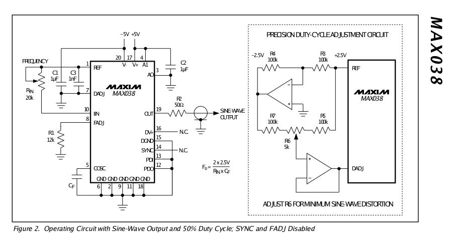
VCO pressure integration scheme.
Big cut VJ
We were faced with a similar problem in experimentally measuring the total
impulse
of very short thrust pulses of attitude control rockets. We ended up using an
integrating voltmeter "gated" to the time of interest. Virtually all digital
voltmeters
generate a frequency based on voltage and counts that over a time (I think)
"Gating" such a circuit over the port open time would give a pretty good
measure of total charge - and that is what you want to base the injected
fuel on.
Just my nickel - butting in
Vance
---------------------------------------
No. I appreciate the advice Vance. No substituted for your extensive
experience in these matters. I will give it some serious thought.
Let's see if I understand this. These voltmeters generate an increasing
signal frequency as a function of the voltage they measure. Is that a correct
statement? Basically it sounds like a Voltage Controlled Oscillator. Gate
the frequency generator on during the time the port is open and read the total
count. I did something similar when I was measuring speed with
my computerized automotive road test system. No software math of
any kind required.
Sounds great. The question is how do we get the number into
Tracy's existing computer. Tracy's computer is currently designed
to take an analog voltage from .5 to 4.5 volts as a measure of
the intake manifold pressure.
I will have to think about this some more.
day later -------------------------------------
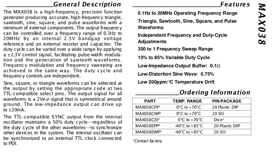
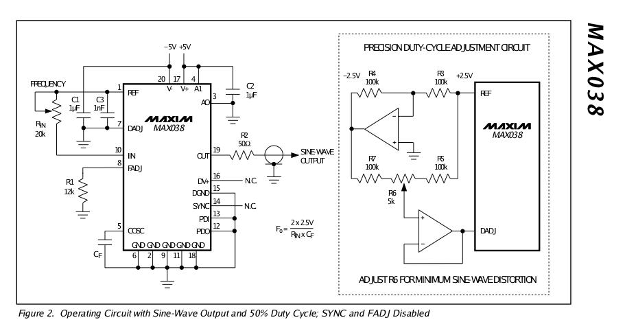
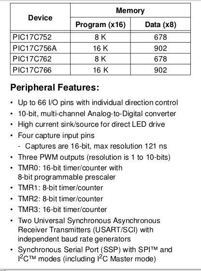
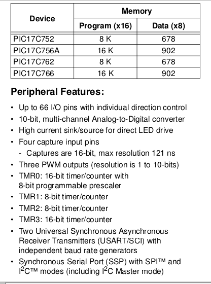
OK here it is. The upside is, it off loads software from the PIC17Cxxx CPU
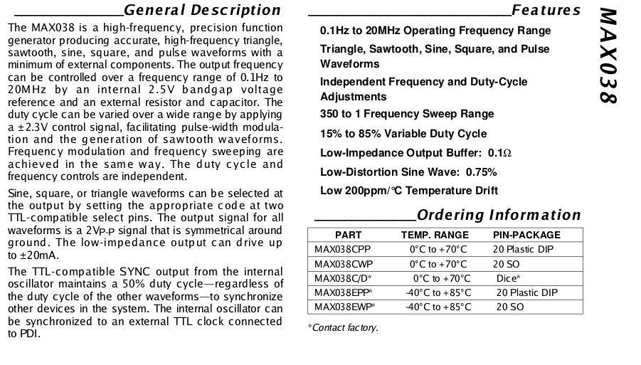
with no need of a lot of pressure samples. The down side is it adds a MAX038
VCO chip to the circuit board. What happens here is the CPU no longer takes in
10 bit analog data from the pressure sensor directly. Instead the pressure
sensor feeds the MAX038 Voltage Controlled Oscillator chip and that in
turn feeds it output frequency to one of the several counter timers in
the PIC17Cxxx single chip CPU chip Tracy uses. The advantage is the count
can be scaled to get a very accurate number of the total pressure
hence air flow in the runner over the actual time the intake port is open.
Did I miss anything? Looks like a good idea but not worth doing
yet for Tracy until p-ports rotary engines become way more wide spread.
His current system designed to measure the pressure in a large
plenum down stream from a butterfly throttle and upstream from side
ports works pretty good and as far as I can tell this adds nothing
to that.
On the other hand it would be a good tuning aid for intake manifold
design if you monitored the pressure data in a runner over the time the
intake port was open, stored it in memory and dumped it to a PC through
the RS232 interface built in to the PIC CPU. The thought being the higher
the total pressure over the RPM range the better the manifold and the
more the HP.
ON THE OTHER HAND!!!
Here is another much simpler and much more accurate method of determining
how much fuel should be injected. Sample the pressure in the intake
chamber directly, right after the intake port closes using the currently
unused apex seal oil injector hole. No software or hardware changes
required other than moving the time the pressure sample is taken.
No effect on the current plenum system other than this is a way more
accurate way of doing it. What you are doing here is directly measuring
the total amount of air that actually made it into the engine.
It will probably even work in a piston engine and is far cheaper
than a mass air flow sensor.
Now that is a multi million dollar patentable device if I ever saw
one and if it were not for the fact you are reading about it at this
very moment :)
Paul Lamar
The Rotary Engine NewsLetter. Powered by Linux.
ACRE NL web site.
http://www.rotaryeng.net
Copyright 1998-2005 All world wide rights reserved.