Hi everyone, I've set a time to meet with the CNC shop to discuss the possibility of
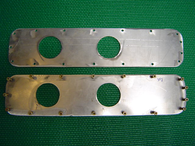
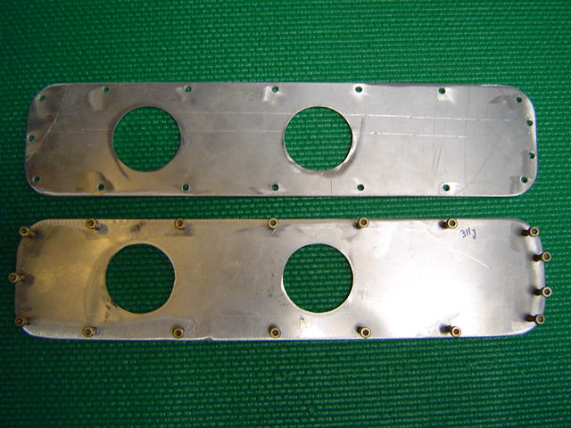
making the spacer. I've had some success with the 3/16 front and back plates. The
plasma leaves a bit of rough edge on the Aluminum, the thermal conductivity of the
aluminum make it much more difficult to cut a clean edge in thicker Al plate. See
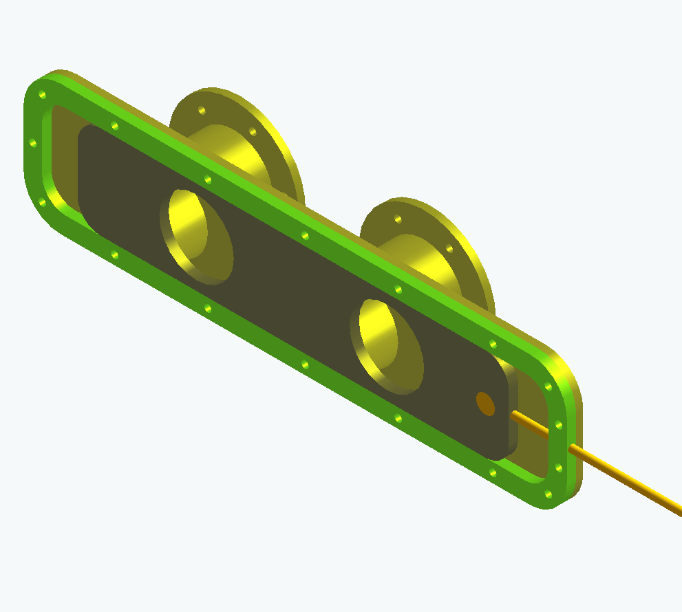
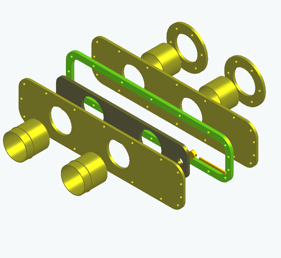
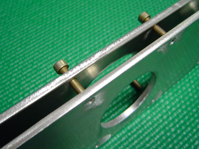
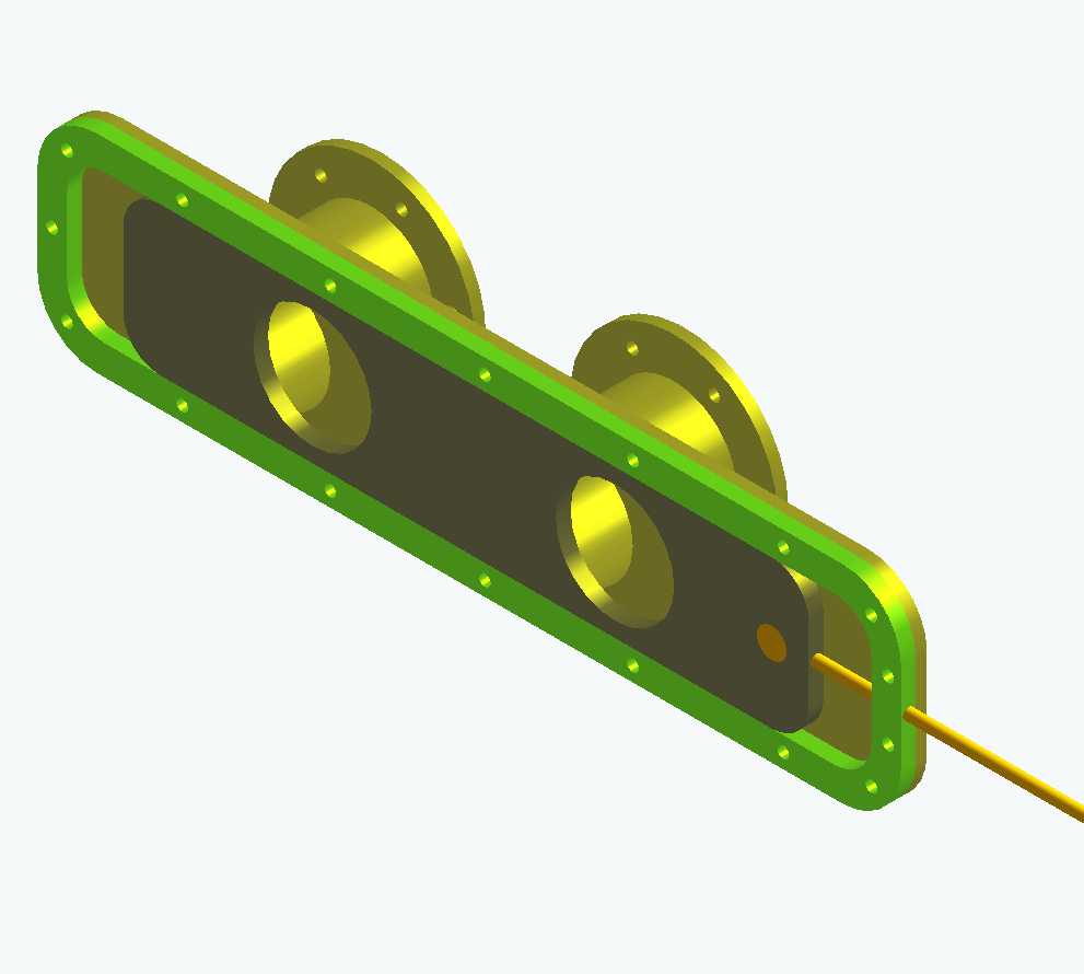
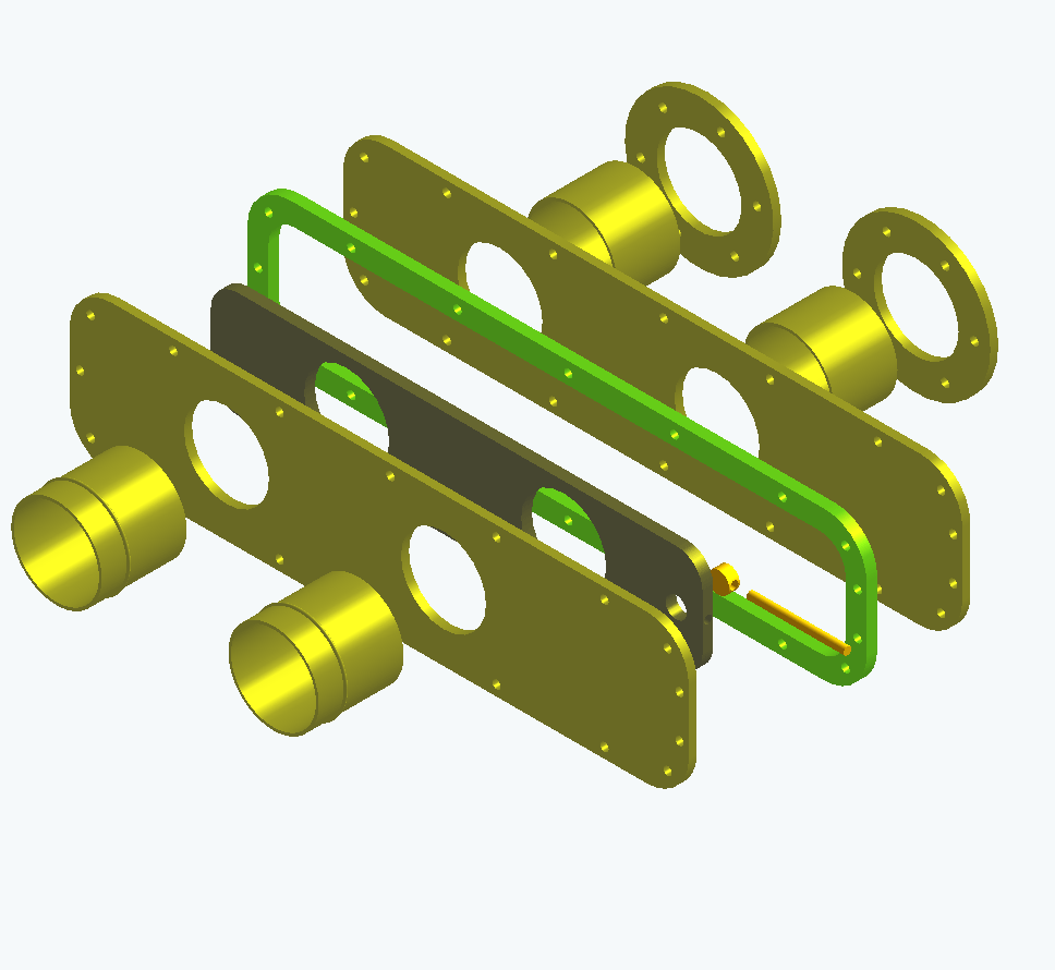
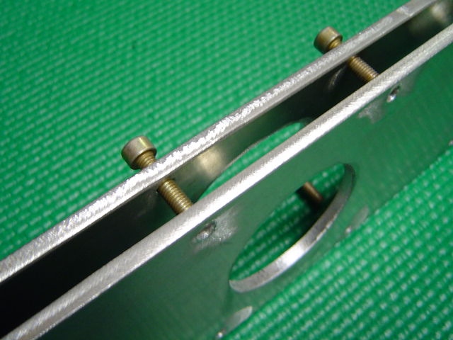
attached Pictures of 3/16 plate cut and cleaned. Also see Rev 9 of the slide
throttle assembly.
Paul, Any comments on the subtle changes to the attach flange or anything else.
Also will we be attaching the manifold tubes to the throttle with silicon hose? How
long should the tubes be, both port side and manifold side? FWIW thats where we are.
T.W.
++++++++++++++++++++++++++++++++++++++++++++++++++++++++++++++
Couple of points on your 3D's Tom. Back to front.
A: The round flanges should be made tall rectangles
so they can share bolts at top and bottom. Also it is
easier to align the bolt holes when bonding the tubes into
the rotor housings. We trial assemble the engine with center,
front and back rotor housings and then bond the tubes in
with pre welded flanges while the inner plate is bolted up.
The inner plate serves as an alignment tool. Been there done that.
B: They should be near the end of the short
tubes that are bonded into the engine so they can be bolted to the
inner slide throttle plate. That is essential as the engine must be
able to be taken apart to overhaul of course.
C: The tubes are two inches in diameter so they should pilot in the
inner plate for alignment and inside smoothness reasons.
D: The outer 2 inch tubes or 180 degree bends can be welded to the outer
plate for compact size length and sealing reasons. Again they should pilot in
the outer plates for a smooth joint. A bit of sanding after welding
will take care of any protrusions.
Paul Lamar
The Rotary Engine NewsLetter. Powered by Linux.
ACRE NL web site.
http://www.rotaryeng.net
Copyright 1998-2005 All world wide rights reserved.