ABS is easier to cut the spacer but you still need a way of doing it.
It could be done on a jig saw with a removable blade. You drill
a hole in the spacer material. Put the blade through it and proceed
to cut the straight lines.
Hang on to the air pump Doug. Makes a great and long lasting vacuum
pump to power your gyros. A bit heavy but well worth it.
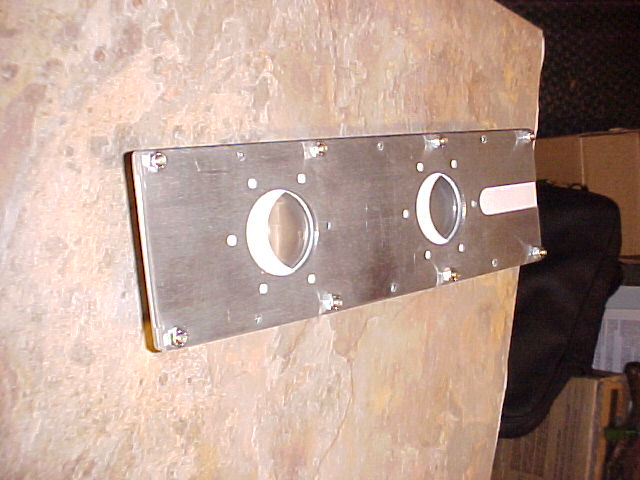
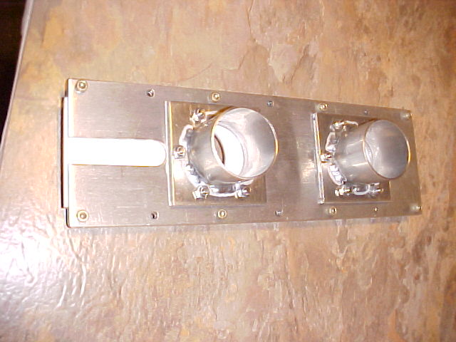
BTW Tom this 3D shows the rectangular flanges.
Ignore the slots in the plates people as Tom idea was to go to
a thicker spacer and attach the slide throttle push pull
rod to the Teflon another way.
Paul Lamar
Yeah, I understood from your explanation. I didn't include the holes in the
middle
of the inside plate for the flange attachment. I'll add those to the program.
T.W.
On the ABS solution. We may be able to use a router and template to cut the
spacer.
If the ABS is appropreate for this use. Match drill the spacer to the front
and back
plates. I can cut the 3/16" 6061 T6 plates and the flange. Maybe thats all we
need
to cut... T.W.
No need to do add the holes to the program. That way one program for both
plates. The outer plates does not have the holes as tubes should
be welded on. People can match drill those side flang holes. The side
flange holes in the back plate also need to be countersunk from the
inside so the Teflon can slide by the flat head screws.
Paul Lamar
Hi Paul,
No vacuums pump needed with electronic gyros:)
I thought about cutting the slider and spacer out of the same piece of
Teflon but gave up on that approach because it would require an exactly
parallel cut to prevent any binding. Bulent's router idea did make me
realize the the edge of both the spacer and the slider can be routered to
any profile so we could give the slider a tongue shape and the spacer the
groove shape. Think flooring boards.
The spacer could be a little thicker material unless a gasket is a must.
The expansion thermal properties of the combination need to be complimentary
so no binding could occur. Does Teflon on Teflon slide well?
As for screws inside the engine side throttle plate. Hmmmm.????
How about replacing those screws with a tapped boss that is spot welded to
the outside of the throttle plate? Four holes on the back of the manifold
rectangular plates would have to be a larger diameter to allow the 'bosses'
to be inserted. The boss height is less than that of the manifold support
plate allowing the use of an Allen bolts and oversize washer to enable it to
be tightened. These four Allen head bolts of course would be inserted
from the back side of the plate.
Doug in Japan
I like vacuum gyros when the electric power goes off :)
Gaskets are a must.
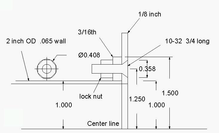
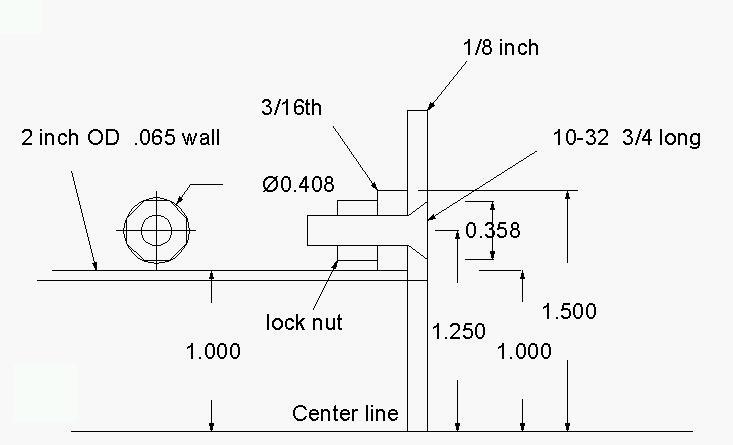
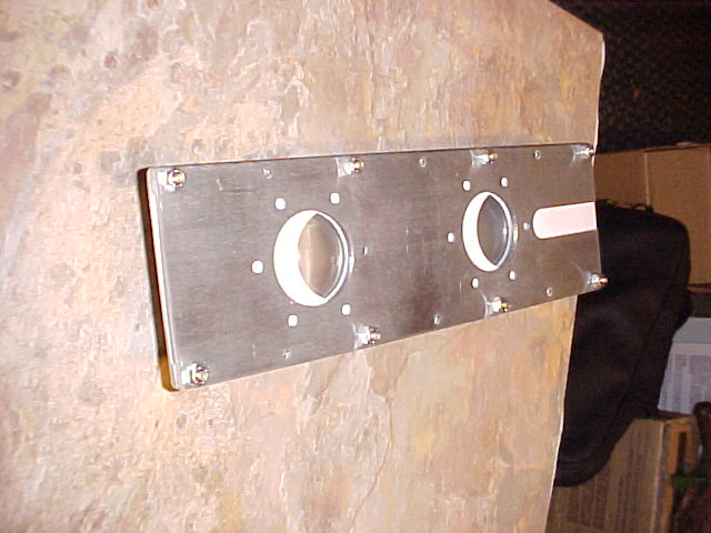
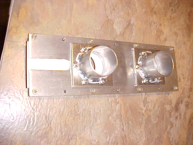
I use all metal locking nuts on the flat head screws. See the picture.
Since the screws are longer than the spacer it is hard for them to
get out. Worst case scenario is the screw works loose and prevents the
throttle from opening all the way.
Paul Lamar
--
The Rotary Engine NewsLetter. Powered by Linux.
ACRE NL web site.
http://www.rotaryeng.net
Copyright 1998-2005 All world wide rights reserved.