Paul
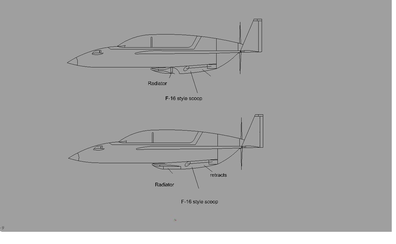
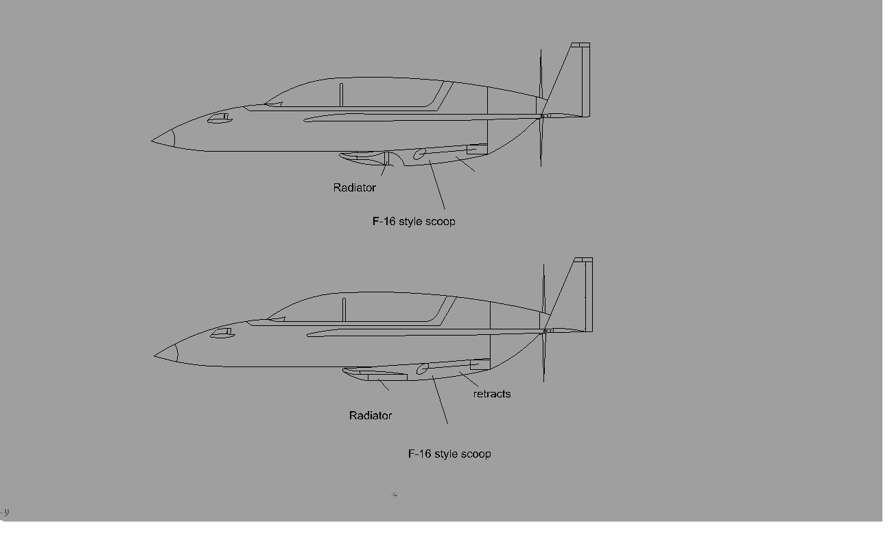
I have attached 2 drawings in auto cad not very good but I think your smart enough to
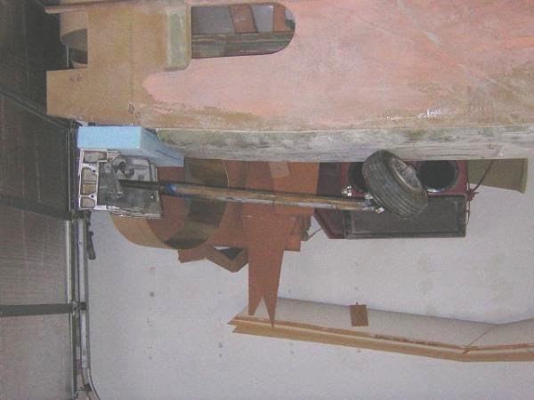
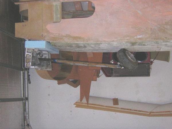
figure it out what I have is a Long Ez with cessna 210 retracts on it you can see it
at
www.myairplane.com click on construction log and then Tonyslongez anyway which of
these 2 drawings would work best for my application and I was wondering if you had
time to draw it 3-d so I can start modeling the intake
Thanks Tony
P.S. I hope to see you at oshkosh.
Hi Tony. for 2D drawings hit shift Print Screen on your keyboard.
Load Windows Paint and press Paste.
Save As jpg. Your 2D dwg will now be in jpg form which
you can attach to your email messages. Saves a lot of work for me :)
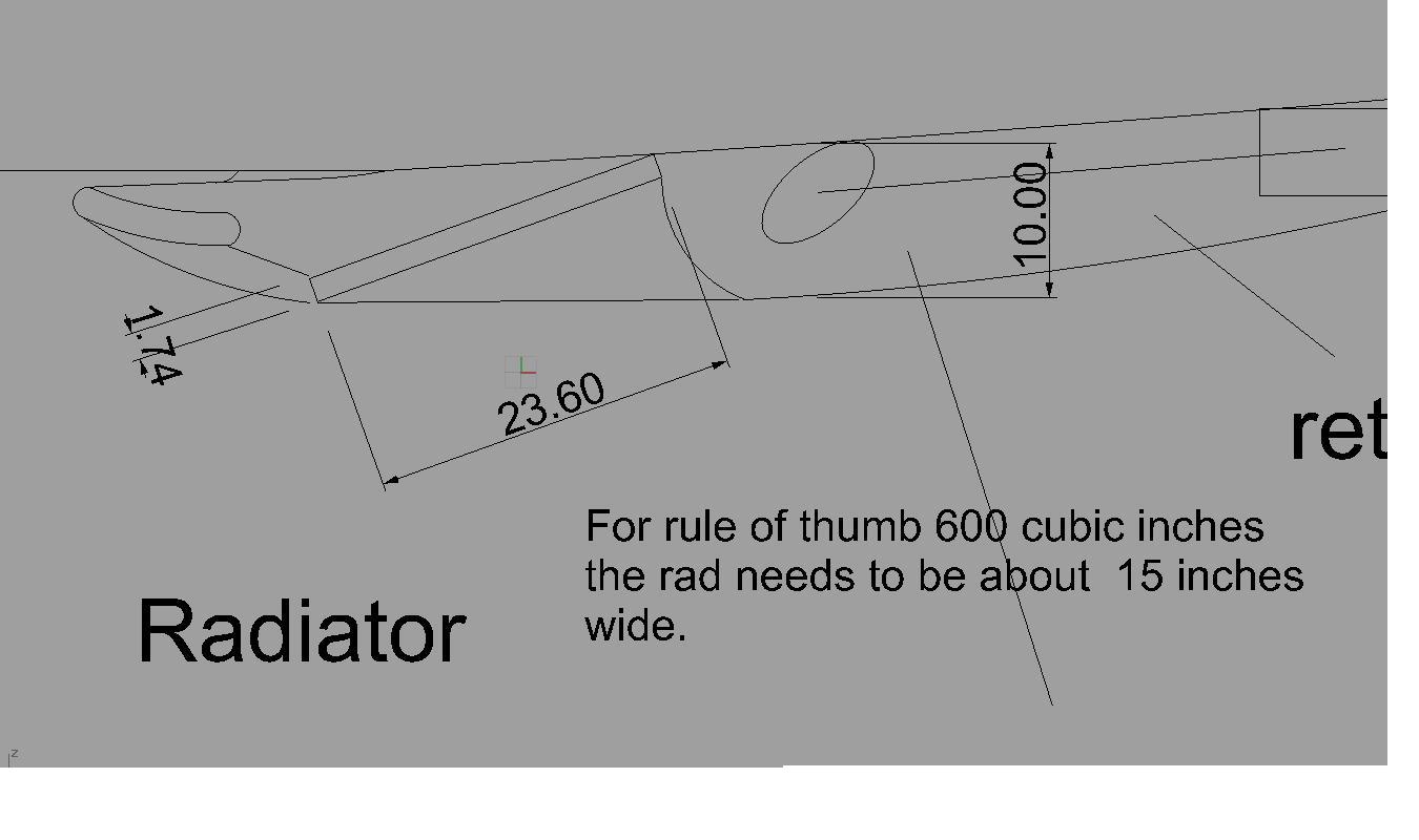
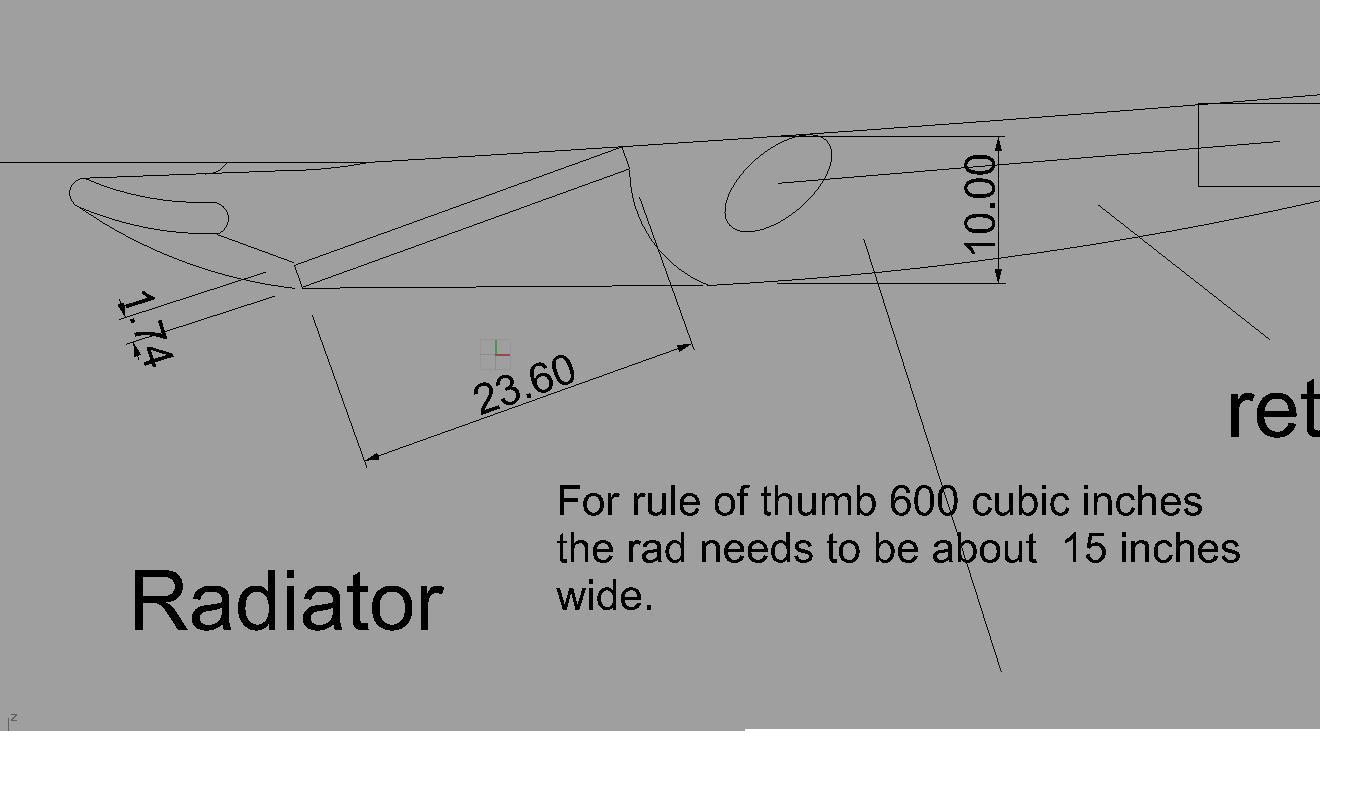
Interesting idea you got there. Rule of thumb it takes about
600 cubic inches of rad volume to cool a rotary so a thick vertical
rad 15 inches wide and 10 inches high would have to be about 4 inches thick.
The first 1/3 of the rad does 3/4 of the cooling and the second
half does 1/4 of the cooling. Another old rule of thumb.
Not too good at our takeoff and climb speed ranges of around
80 120 MPH as it takes a lot of dynamic pressure to force air
through a thick rad. It will work but you might not be happy
on a hot day.
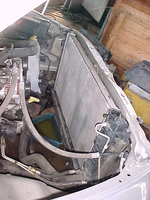
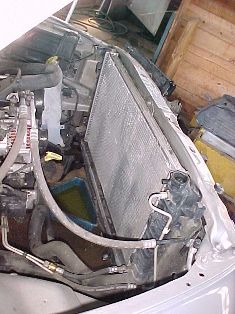
Modern highly efficient heat exchangers tend towards large frontal area with
minimal thickness. This late model Dodge PU rad is a good example. So laying
it down at an angle seems to be the best solution. I modified your drawing
to show the dimensions and a slightly better configuration.
Paul Lamar
The Rotary Engine NewsLetter. Powered by Linux.
ACRE NL web site.
http://www.rotaryeng.net
Copyright 1998-2005 All world wide rights reserved.