Well, my install of an S-Beam with the RD1C is not going smoothly.
After receiving the correct flex plate, it was only another 5 minutes
before I ran into additional serious problems.
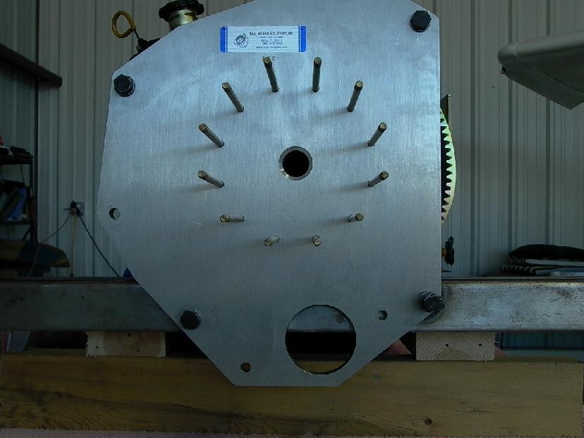
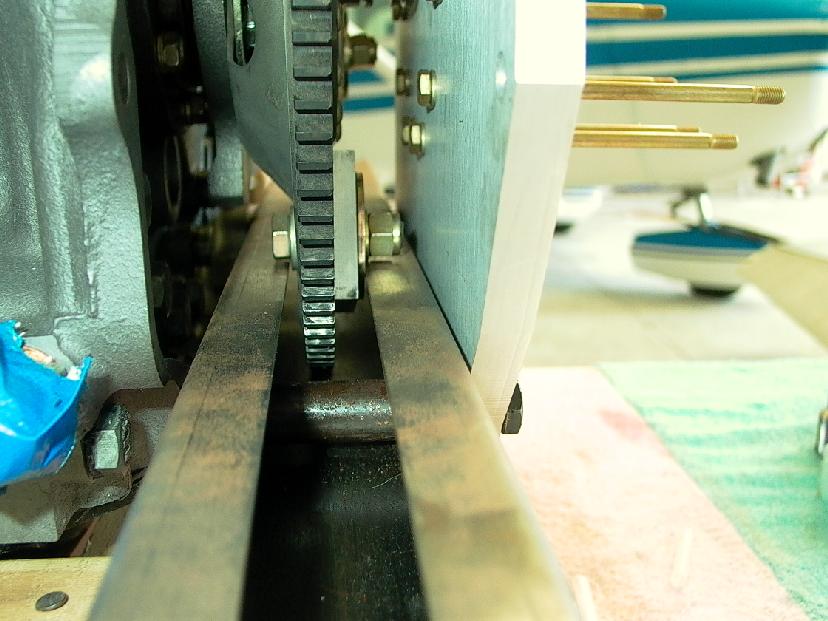
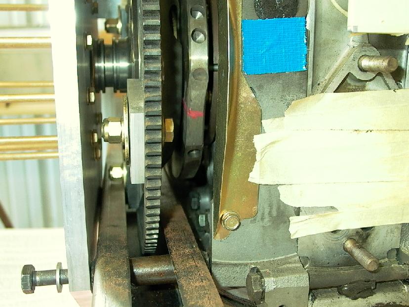
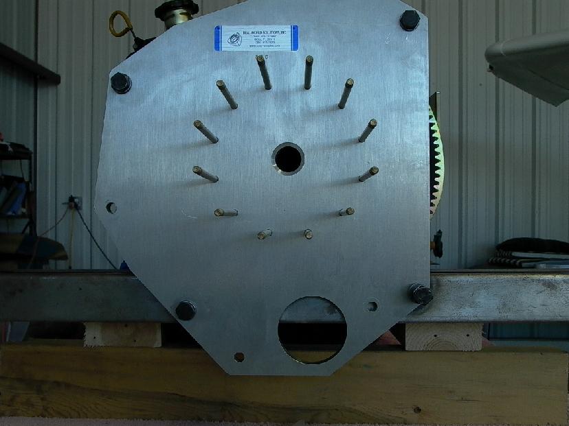
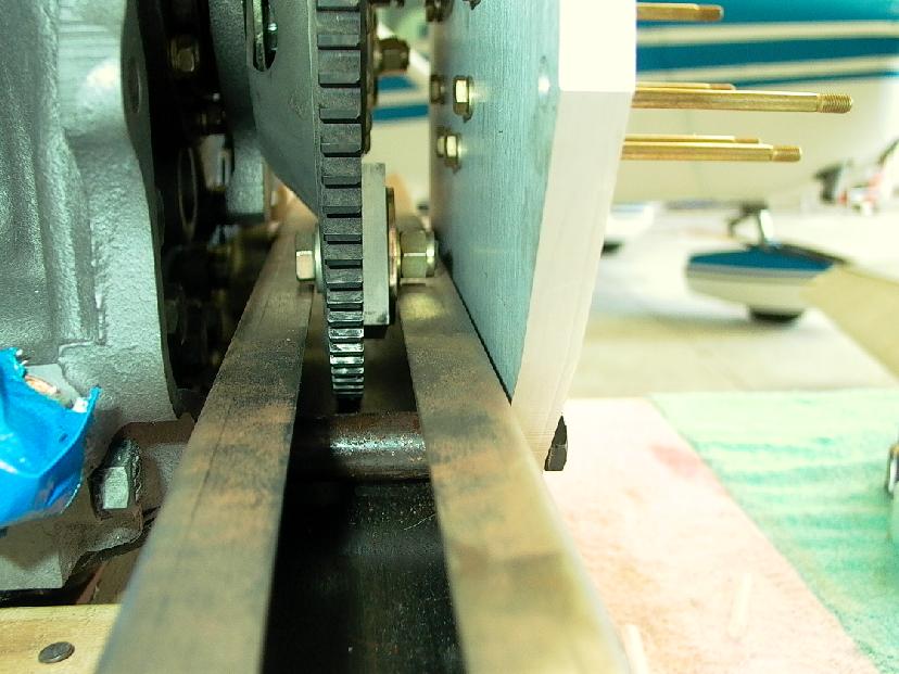
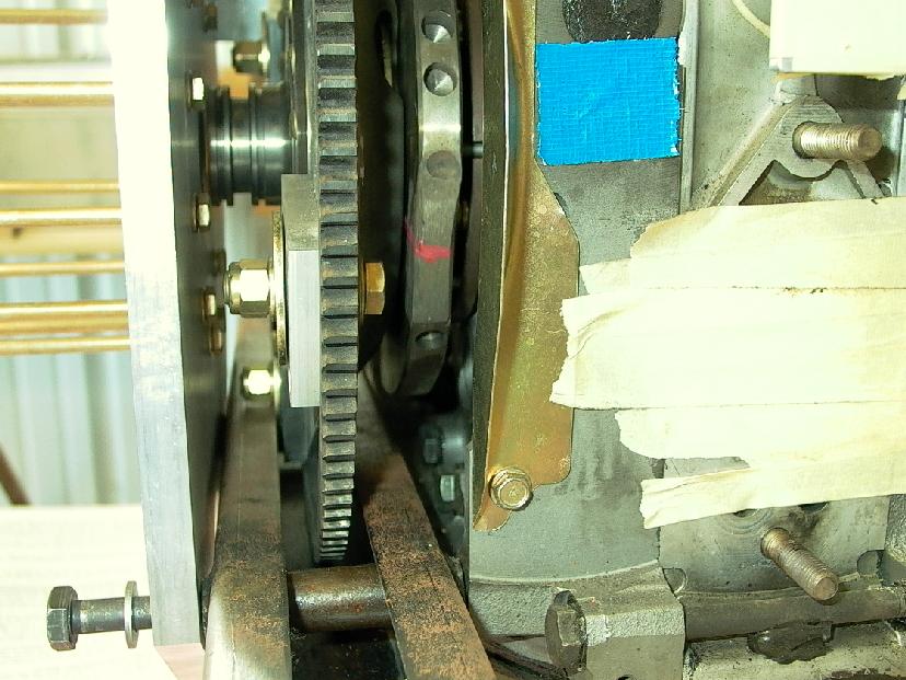
In the attached photos, you can see 3 issues I am grappling with. The
first is that there is a significant interference between the RD1C's
damper plate bolts and the channel in the S-Beam. As you can see, the
bolts would require a much larger channel to go through. I have not
yet measured the interference, but a quick look indicates a widening
almost to to edges of the u-channel. I am very concerned that this
widening would weaken the S-Beam to the point where it could no longer
support the engine in a 6-G landing without buckling.
In the second photo, the next problem is apparent. Tracy's design
calls for the starter to be mounted at approximately the 5:30
position. In the case of an S-Beam, this access is completely blocked
by the S-Beam itself. Given that Tracy has minimized the material in
his mounting plat design, I think it will be a challenge to find a
starter mounting position without redesigning the mounting plate from
scratch -- not something I am wild about doing. I think this starter
position issue was a known-issue from a few months back, but can't
remember what the final solution was.
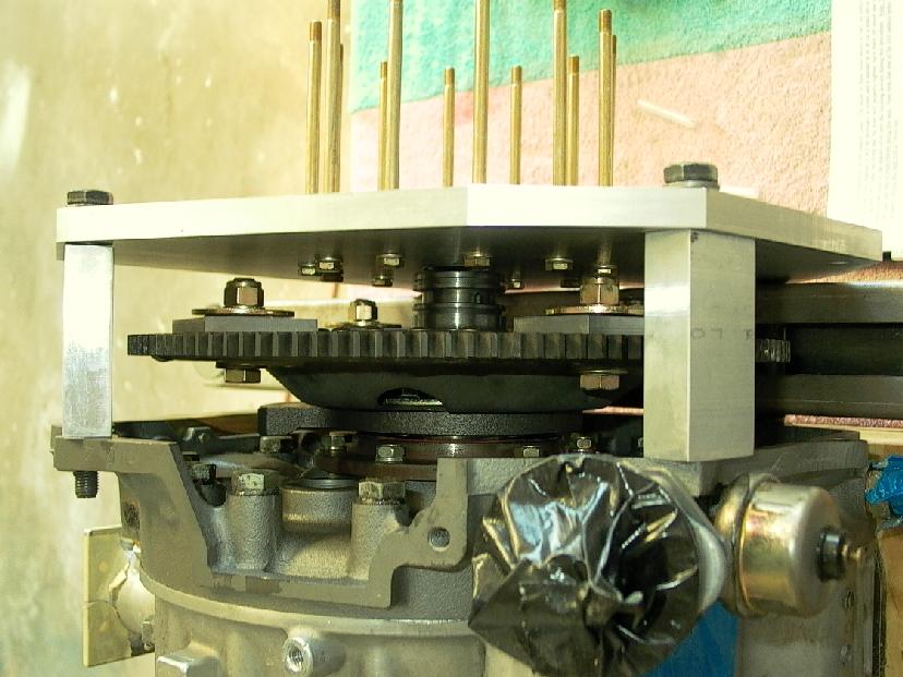
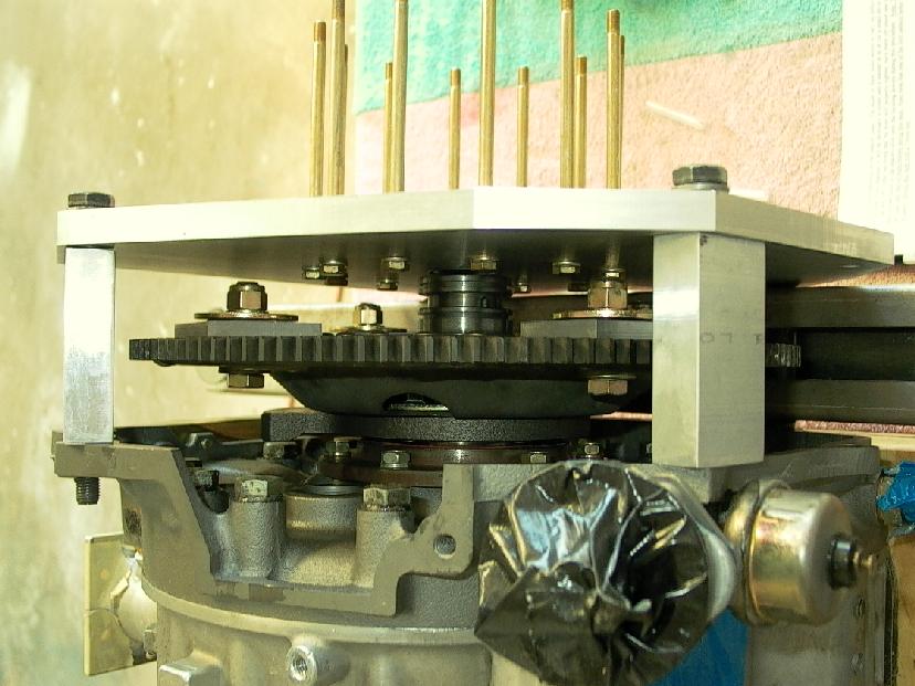
Finally, I see in the photos of another S-Beam installation (not sure
whose) that Tracy's spacers in the RD1? have been replaced by
individual steel tubes. While it is necessary to replace the spacers
due to the S-Beam using 2 of the bolt holes, I am unconvinced that
steel tubes will provide equivalent torsional resistance compared to
the blocks of aluminum which are present in Tracy's base design. I
wonder whether it will be necessary to fabricate blocks which span
alternate bolt holes.
So, I am at a dead stop once again. I am not seeing any solutions
which don't involve serious reworking of the RD1C mounting scheme,
including compromise of the strength of the S-Beam. Any ideas on what
to do about my dilemma?
Mark
Since I am not at the hangar right at the moment
I can't measure my damper plate to see what happened. In other words
I don't have my damper plate in front of me at the moment. It is 60 miles
away unfortunately. The damper plate and bolts should clear the top flanges.
Could you measure that radius to the center of damper bolts for me. From
bolt hole center to center will also work as it is a perfect square.
Also please measure the OD of the ring gear for me.
Don't panic we will fix it. I think the steel bushings were
welded in a bit too low in the beam. The left side steel bushing can
intersect the top flange with no loss in strength. Probably my fault
on the drawing. We can make a new beam for you with the steel bushings
in the right place. We will move the bushings up a bit. That will move
the baem down a bit. No cost to you. Sorry about that.
The starter reposition was a known issue. I will modify Tracy's 1/2 inch
adapter plate for the side mounted starter no charge. You will have to
send me your plate.
The mounting beam is more than adequate for torsional strength as the
prop torque of about of about 560 foot pounds max (assuming the p-port engine
is generating 200 foot pounds max and the psru is 2.8:1) goes directly into
the beam and then into the rubber motor mount bushings. Round spacers could
be used in the rest of the holes if you wish. Never the less on
the right side a 1/2 inch rectangular plate spacer can still be used between
the right most hole and the upper right most hole.
Paul Lamar
The Rotary Engine NewsLetter. Powered by Linux.
ACRE NL web site.
http://www.rotaryeng.net
Copyright 1998-2005 All world wide rights reserved.