> > Well, my install of an S-Beam with the RD1C is not going smoothly.
> > After receiving the correct flex plate, it was only another 5 minutes
> > before I ran into additional serious problems.
> >
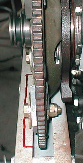
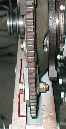
> > In the attached photos, you can see 3 issues I am grappling with. The
> > first is that there is a significant interference between the RD1C's
> > damper plate bolts and the channel in the S-Beam. As you can see, the
> > bolts would require a much larger channel to go through. I have not
> > yet measured the interference, but a quick look indicates a widening
> > almost to to edges of the u-channel. I am very concerned that this
> > widening would weaken the S-Beam to the point where it could no longer
> > support the engine in a 6-G landing without buckling.
> >
> > In the second photo, the next problem is apparent. Tracy's design
> > calls for the starter to be mounted at approximately the 5:30
> > position. In the case of an S-Beam, this access is completely blocked
> > by the S-Beam itself. Given that Tracy has minimized the material in
> > his mounting plat design, I think it will be a challenge to find a
> > starter mounting position without redesigning the mounting plate from
> > scratch -- not something I am wild about doing. I think this starter
> > position issue was a known-issue from a few months back, but can't
> > remember what the final solution was.
> >
> > Finally, I see in the photos of another S-Beam installation (not sure
> > whose) that Tracy's spacers in the RD1? have been replaced by
> > individual steel tubes. While it is necessary to replace the spacers
> > due to the S-Beam using 2 of the bolt holes, I am unconvinced that
> > steel tubes will provide equivalent torsional resistance compared to
> > the blocks of aluminum which are present in Tracy's base design. I
> > wonder whether it will be necessary to fabricate blocks which span
> > alternate bolt holes.
> >
> > So, I am at a dead stop once again. I am not seeing any solutions
> > which don't involve serious reworking of the RD1C mounting scheme,
> > including compromise of the strength of the S-Beam. Any ideas on what
> > to do about my dilemma?
> >
> > Mark
> >
> > Since I am not at the hangar right at the moment
> > I can't measure my damper plate to see what happened. In other words
> > I don't have my damper plate in front of me at the moment. It is 60
> > miles
> > away unfortunately. The damper plate and bolts should clear the
> > top flanges.
> > Could you measure that radius to the center of damper bolts for me.
> > From
> > bolt hole center to center will also work as it is a perfect square.
> > Also please measure the OD of the ring gear for me.
> >
> > Don't panic we will fix it. I think the steel bushings were
> > welded in a bit too low in the beam. The left side steel bushing can
> > intersect the top flange with no loss in strength. Probably my fault
> > on the drawing. We can make a new beam for you with the steel bushings
> > in the right place. We will move the bushings up a bit. That will
> > move
> > the beam down a bit. No cost to you. Sorry about that.
> >
> > The starter reposition was a known issue. I will modify Tracy's
> > 1/2 inch
> > adapter plate for the side mounted starter no charge. You will have to
> > send me your plate.
> >
> > The mounting beam is more than adequate for torsional strength as the
> > prop torque of about of about 560 foot pounds max (assuming the p-
> > port engine
> > is generating 200 foot pounds max and the psru is 2.8:1) goes
> > directly into
> > the beam and then into the rubber motor mount bushings. Round
> > spacers could
> > be used in the rest of the holes if you wish. Never the less on
> > the right side a 1/2 inch rectangular plate spacer can still be
> > used between
> > the right most hole and the upper right most hole.
> >
> > Paul Lamar
> >
> > Looks like a screwed up big time. Long story but way back when we
> > decided to do this motor mount I did not have a real good drawing
> > on Tracy's adapter plate as I was using ACAD V12 for DOS at the time.
> > Tracy was using something else. I never tried loading his DXF
> > file into Rhino until now but Rhino, bless its little heart, had no
> > trouble
> > with Tracy's DXF so I was able to read the dimensions by zooming in.
> >
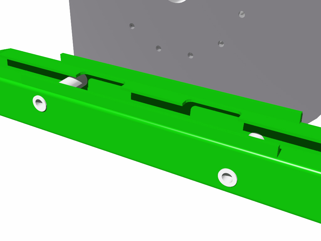
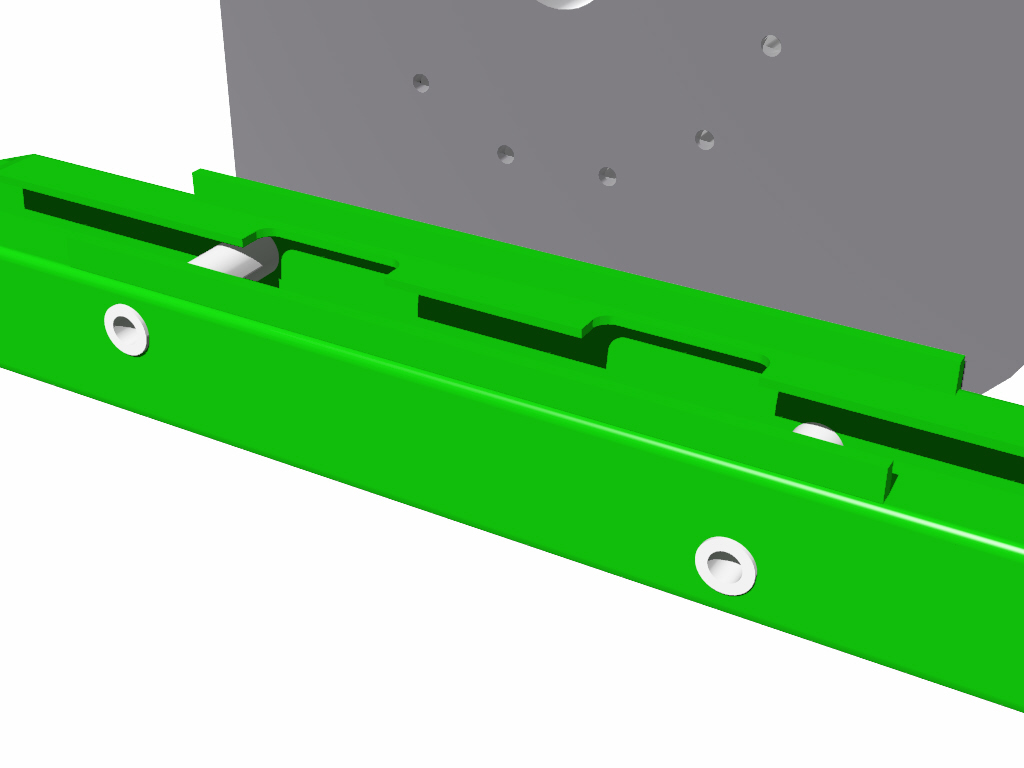
> > Here is the worst case fix. Just a couple of .065" ears on the top of
> > the beam for the left bolt. This is looking at the plate
> > from the engine side. Right bolt can recessed and centered on the top
> > flange. I am not sure until I get your dimension whether we will
> > have to go this far down with the beam.
> >
> > I guess Jerry did not have Tracy's gear box at the time to check
> > the fit.
> >
> >
> > Here is how Al Gietzen relocated his starter.
> >
> > Paul Lamar
>
> Paul, the S-beam fits my engine and Tracy's gear box perfectly. I
> have published about a million pictures of it, so I won't send more
> unless you ask me too. I am not saying I did not make some error in
> construction, but the S beam I sent to Mark was bolted on the front
> of my mock up engine without problem. I took the measurements for the
> bushing holes directly from the end iron housing ( jigged up in the
> mill and used the readout (.xxxx) for the measurements). Jerry
>
> Did you have the dampener on the flex plate Jerry?
> Maybe Tracy changed the size of the dampener plate.
>
> Paul Lamar
Jerry is correct that the s-beam fit the engine correctly -- the bolts
slid in perfectly. And, after removing the flex-plate ears, the flex
plate was dead-center of the s-beam channel. The flex dampener plate
also fits inside the channel comfortably. The gotcha is the bolts
which attach the dampener plate -- those aren't close to fitting.
I will perform all measurements today. I will also remove Tracy's
mounting plate, but leave the dampener & sbeam on so I can get some
good shots from head-on of the bolt interference. I'm not sure if
repositioning the bolt holes in the sbeam upward can eliminate the
interference -- it might be that the upper bolt hole can't move far
enough up. In any case, I will measure & photo as necessary to be
able to calculate this.
On another subject, I have found a prop which can be used for the
engine testing. It is off another Mustang II & should have the exact
bolt pattern as on the RD1C. Couldn't fly it (wrong pitch for the HP)
but am I correct in believing it would be a sufficient load to prevent
the engine from over-speeding?
Thanks, guys-
Mark
Lowering the beam and adding ears on top for the spacers will work for sure.
We have come up with another solution that might work. We will narrow the upper
flanges to 1/4 wide and add a strip of 1/4 inch 4130 on top. Also turn
the bolts around with the nut towards the engine. I think that will
give us a bit more room for the 1/4 inch flange modification based
on this picture. Jerry is checking this idea as we speak.
No problem on the prop. When the tips approach supersonic it is like
running into an RPM brick wall.
Paul Lamar
Looks like all we will need is a couple of notchs Mark. The reduced flange
width can then be reinforced with a tiny pieces of steel around
the notchs. Sorry about all this. My fault for not making
a better detailed drawing.
Paul Lamar
Ok, I have driven out to the hangar & measured things galore.
Naturally, I left the paper with all the measurements at the hangar.
BUT - since I have a habit of doing boneheaded things like this, I
also took photos with the rules in place. And these I have!
Since there are so many hi-rez photos for this, instead of killing
everyone's email I have posted them on my web site. Here are the
links to view them:
http://www.supinski.net/IMG_2251.JPG
http://www.supinski.net/IMG_2252.JPG
http://www.supinski.net/IMG_2254.JPG
http://www.supinski.net/IMG_2255.JPG
http://www.supinski.net/IMG_2257.JPG
http://www.supinski.net/IMG_2258.JPG
http://www.supinski.net/IMG_2259.JPG
http://www.supinski.net/IMG_2260.JPG
http://www.supinski.net/IMG_2262.JPG
http://www.supinski.net/IMG_2263.JPG
http://www.supinski.net/IMG_2264.JPG
http://www.supinski.net/IMG_2265.JPG
http://www.supinski.net/IMG_2269.JPG
http://www.supinski.net/IMG_2270.JPG
Paul, all the measurements you asked for are there. Also, I reversed
one of the bolts & showed how it looks on both sides. The measurement
for the ring gear is off my wrong year gear. It is the same diameter
as the correct one tho.
Assuming that some rework is going to be necessary, I brought the
sbeam and Tracy's mounting plate home with me.
Thanks,
Mark
You are not alone Mark :)
I think we have it figured out. Jerry assembled his and found
the problem. Here is the solution. Find a tig welder
locally and send me the bill. My fault for not catching this.
Cheaper than shipping it back and fourth.
Paul Lamar
The Rotary Engine NewsLetter. Powered by Linux.
ACRE NL web site.
http://www.rotaryeng.net
Copyright 1998-2005 All world wide rights reserved.