> I had a long talk with Tracy on this subject.
> The question is what is the true manifold pressure. We need to know
> that number to set the pulse width of the fuel injectors. Since
> Tracy samples it for only a millisecond or so it could be affected by
> a lot of factors. We know there are pressure pulses in intake
> and exhaust systems. The question is; what part of the pressure
> curve is occurring when Tracy samples the pressure?
>
> Tracy samples the pressure for firing the injectors on rotor two
> right after (within a few microseconds) he fires rotor
> one's ignition plugs (about 20 degrees BTDC). So far I have not been
> able to talk him into taking many samples and averaging the data.
>
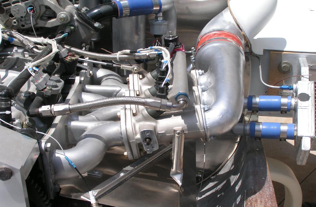
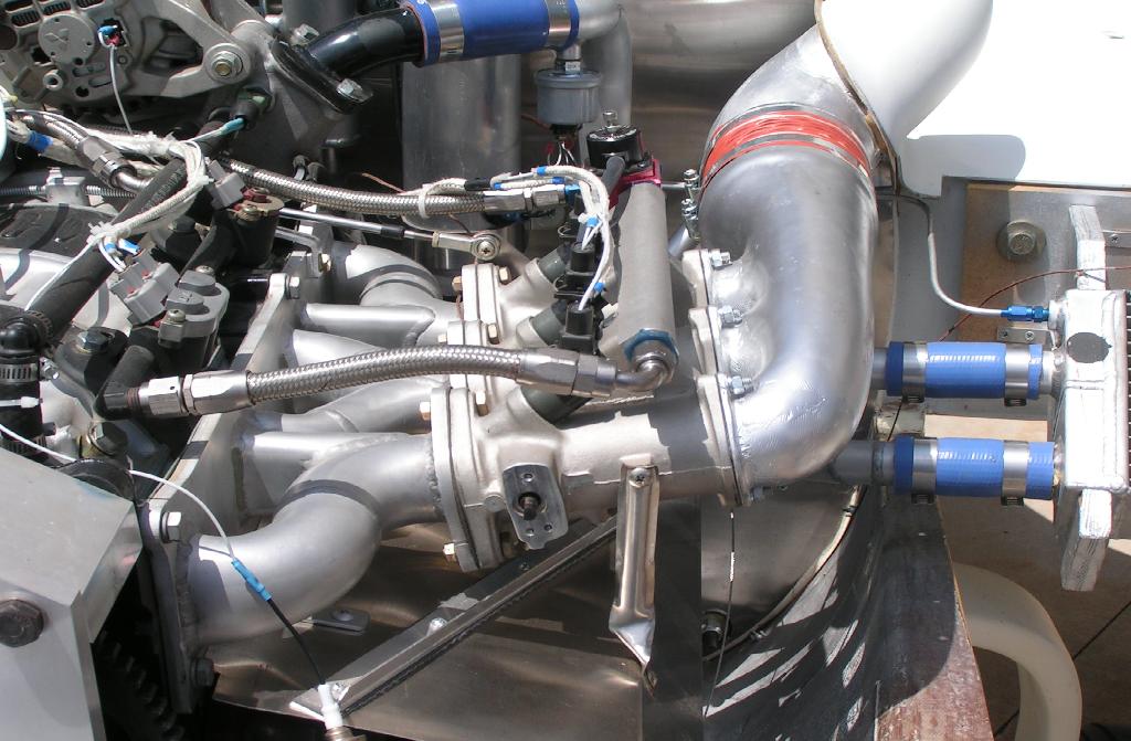
> We discussed how to measure the pressure wave in the p-port intake
> manifold
> as a function of e-shaft angle during one cycle per revolution of the
> e-shaft. The max pressure will occur at different times depending
> on the RPM and the length and diameter of the runners. So far
> suggestions
> have been; feeding the output of the high speed pressure sensor into a
> PC
> audio input card or the microphone jack of a note book computer. Tracy
> pointed out the problem with that are those are AC inputs and we need
> absolute numbers from the pressure sensors. We also need to relate
> them to the ignition pulse. That led to using a storage oscilloscope
> instead.
>
> The price of battery powered hand held storage oscilloscope have
> dropped
> recently and they are fast enough to do this job. At 7500 RPM it takes
> the e-shaft 8 milliseconds to make one revolution. In other words
> that is only 125 revolutions per second. Since the response times
> of the pressure sensors is only 1 Kilohertz most hand low cost held
> oscilloscopes are fast enough to do this. They are also fast enough
> to measure the pulse width of a fuel injector if you want to
> use them for that. This device will help greatly when designing and
> developing intake manifolds.
>
> Here is a intake manifold pressure pulse from a Mazda tech paper
> SAE 841017 on P-port intake manifolds.
>
> Here also is a pdf file for some hand held storage oscilloscopes.
>
> When Mark gets his p-port engine in his Mustang II airplane I will pop
> over to Denver and help tune it with what ever test equipment
> I can beg, borrow, bring, or steal :)
>
> Paul Lamar
Hi Paul,
It seems like there are two system design choices available. The first
is to leave Tracy's computer alone and provide some mechanical low pass
filtering for the sensor. A long, thin tube feeding a small air tank,
feeding (through a small orifice) another thin tube to the sensor would
probably work - resistive to resonant pulses. This will get a stable
signal for the computer to look at - average out the ups and downs of
the manifold pressure during the engine's cycle, regardless of RPM.
That way the computer can have a realistic value for the amount of air
available to be injested by the engine.
A few nice things about approach are that it's dirt-simple, and it works
throughout the RPM range.
As I think you have suggested, taking a short snapshot of the MP at a
fixed point in time each cycle may mean that the pressure is low at some
RPM values and erroneously high at others. That can probably be tuned
out via MAP vs RPM vs fuel curve, but it's clunky.
The other approach is as you suggested - sample the MP sensor often
enough to get a realtime waveform of MP. I can't see a real benefit to
this except that it might allow you squirt the fuel into the intakes at
a more optimized time during the cycle - allowing better charge
distribution, or something like that. That's going to take a fair
amount of time to dial in, I think.
From the standpoint of fuel delivery requirements, I can't see the need
to get a high resolution picture of MP. Even if there were a 10 cycle
delay in the response time of the sensor, it wouldn't have an impact on
engine performance. I'm probably missing something.
One other concern I might have is that of mechanically damping the input
signal to the MP sensor. I could imagine generating a resonance which
could really wack things out. That might be a bit of a concern if you
try to get a high resolution picture of MP.
Regards,
Matt-
VE N34RD, C150 N714BK
can you use the standard auto mass air flow sensor to only get an idea
what the fuel requirements are ? not for use on the airplane only for
testing and setting up the fuel requirements. tom kimsey
That is a good idea Tom. I am sure we would learn a lot.
Paul Lamar
I still think there is an electronic solution to your problem. I have the
development kit for the Cypress Micro Psoc processors. The microchips cost
less than $10 and have all the analog and digital circuitry to do what you
need. What about using a peak detector? and let the microprocessor's drain
the capacitor when the MP sensor drops below some threshold? You probably
would have to add an external diode and capacitor.
Del Johnson
I think that will work. Al Gietzen has a similar situation with his
three rotor engine. I.E. No plenum downstream from the throttle plates.
Much like a P-port engine. He is "T" ing together vacuum taps from just two
of the three runners and so far he has had good success on the dyno.
He claims the EGT tracks well on all three rotors. Of course things
could change when he gets a prop load in the air at speed but so far
it seems to be running great on the ground. Al is also using Tracy
computer. Tracy claims if it runs well under static prop load
conditions it will be OK in the air.
Paul Lamar
--
The Rotary Engine NewsLetter. Powered by Linux.
ACRE NL web site.
http://www.rotaryeng.net
Copyright 1998-2005 All world wide rights reserved.