> > >>> >
> > >>> > > Big Snip
> > >>> > >
>
>
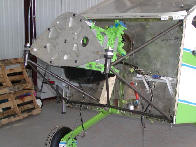
> This fix is probably best for new motor mounts using existing beams.
> It lowers the beam and inch or so and consequently it raises
> the thrust line an inch or so if the motor mount is already welded
> up. If new mount is being made the mount can be adjusted to get the
> thrust line in the right place. The four plates are .065 thick
> 4130. Best to put the nuts on the back side of the flex
> plate.
>
> Paul Lamar
>
> Also clears the counter weight.
>
> Paul Lamar
>
> The Rotary Engine NewsLetter. Powered by Linux.
> ACRE NL web site. http://www.rotaryeng.net
> Copyright 1998-2005 All world wide rights reserved.
>
>
Hi Paul,
Since the box beams were bent up to match the width of Tracy's spacers,
the tabs would make it too wide, so the existing beams couldn't be used
with this mod. How about welding a supporting structure to the bottom
of the beam in the center where the box structure has been cut back? I
would think the box could be cut back to a 'U' section in the center if
the right strengthing member were added to the bottom.
Bob W.
Please measure your beam width for me Bob. Should only be 2.70 inches wide.
The spacing between plate and engine should be 3.050 or 3.080 I forget
which.
If the spacer lengths are less than that you might have a problem with your PSRU.
Paul Lamar
It looks like the design is a little different than I thought. Now I
see that the spacer goes all the way thru the box instead of being
internal. That makes sense as the box dimensions aren't critical.
Sorry for jumping the gun there.
I have ordered a S-beam from Jerry, but don't have it yet. I'm
using the MM plate at the moment. I want the option of converting to
the S-beam later, but after the plane is flying! :)
Bob W.
--
http://www.bob-white.com
N93BD - Rotary Powered BD-4 (real soon)
Prewired EC2 Cables -
http://www.roblinphoto.com/shop/
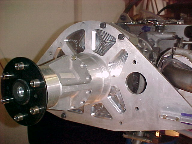
The design is rather subtle. One must remember that the gear box greatly
increases the torque on the prop. In the case of the 2.8:1 gear box the
prop torque with a P-port engine can be as high as 560 ft pounds.
This torque must be reacted by the motor mounts. If the motor mounts
are on the engine, such as some bed mounts are, the torque must pass
through the spacers. If the motor mounts are on the PSRU plate, like
yours and my current set up are, the spacers only see 200 ft pounds max. Same
with the S beam. The torque load goes directly into the S beam through
the two 10 mm bolts and then into the motor mounts. The wide spread
rubber bushings then see a reduced torque load of about +/- 250 pounds.
Since engine, psru and prop weigh only about 250 pounds one
rubber mount has - 125 pounds and the other +375 pounds. This is only when
the engine is generating peak torque. This is peanuts when it comes to
a six G pull up or a hard landing. In that case the bushings are seeing
750 pounds each or more. Up to 900 pounds depending on the exact weight
of the engine and the torque being generated. This why it is so important
to design and weld in the reinforcements around the larger top hole properly.
At full power, 200 MPH and net prop HP of 160 there is also a radial
or prop thrust load on the mounts of 288 pounds total. Each mount would
then be seeing half that or 144 pounds in the radial
fore and aft direction.
BTW This simple and brilliant MM idea was invented by, the designer of the Piper
Malibu and used on the Questair Venture, Jim Griswald. Those
that have flown in Questair Ventures tell me it is one of the smoothest
airplanes flying.
Paul Lamar
The Rotary Engine NewsLetter. Powered by Linux.
ACRE NL web site.
http://www.rotaryeng.net
Copyright 1998-2005 All world wide rights reserved.