> >> > > >>> >
> >> > > >>> > > Big Snip
> >> > > >>> > >
> >> >
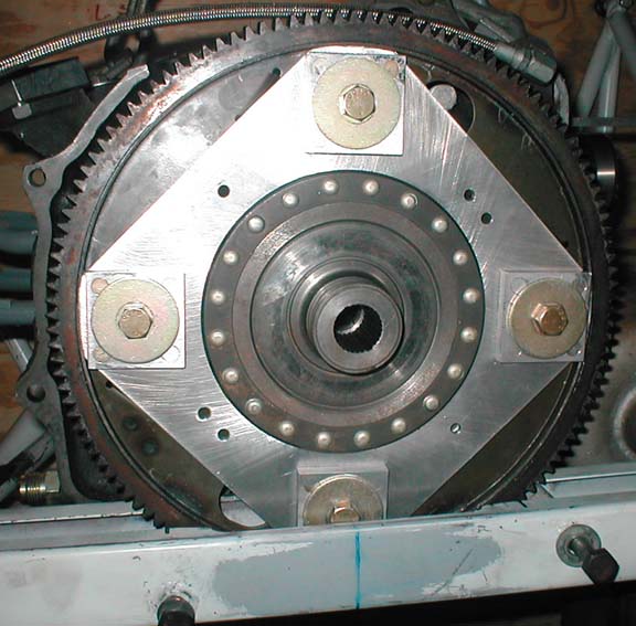
> >> > > This fix is probably best for new motor mounts using existing
> >> beams.
> >> > It lowers the beam and inch or so and consequently it raises
> >> > the thrust line an inch or so if the motor mount is already welded
> >> > up. If new mount is being made the mount can be adjusted to get the
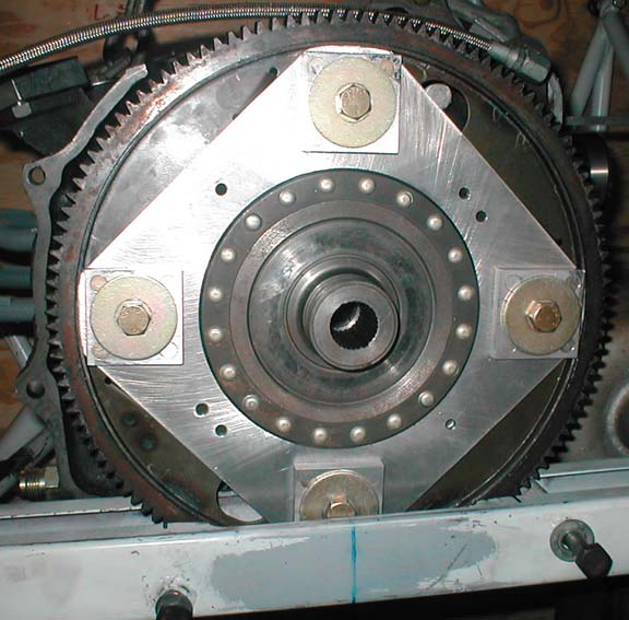
> >> > thrust line in the right place. The four plates are .065 thick
> >> > 4130. Best to put the nuts on the back side of the flex
> >> > plate.
> >> > > Paul Lamar
> >> > > Also clears the counter weight.
> >> > > Paul Lamar
> >> > > The Rotary Engine NewsLetter. Powered by Linux.
> >> > ACRE NL web site. http://www.rotaryeng.net
> >> > Copyright 1998-2005 All world wide rights reserved.
> >> > > Hi Paul,
> >> Since the box beams were bent up to match the width of Tracy's
> >> spacers,
> >> the tabs would make it too wide, so the existing beams couldn't be
> >> used
> >> with this mod. How about welding a supporting structure to the
> >> bottom
> >> of the beam in the center where the box structure has been cut
> >> back? I
> >> would think the box could be cut back to a 'U' section in the
> >> center if
> >> the right strengthing member were added to the bottom.
> >> Bob W.
> >> Please measure your beam width for me Bob. Should only be 2.70
> >> inches wide.
> >> The spacing between plate and engine should be 3.050 or 3.080 I
> >> forget
> >> which.
> >> If the spacer lengths are less than that you might have a problem
> >> with your PSRU.
> >> Paul Lamar
> >>
> >
> > It looks like the design is a little different than I thought. Now I
> > see that the spacer goes all the way thru the box instead of being
> > internal. That makes sense as the box dimensions aren't critical.
> > Sorry for jumping the gun there.
> >
> > I have ordered a S-beam from Jerry, but don't have it yet. I'm
> > using the MM plate at the moment. I want the option of converting to
> > the S-beam later, but after the plane is flying! :)
> >
> > Bob W.
> >
> > --
> > http://www.bob-white.com
> > N93BD - Rotary Powered BD-4 (real soon)
> > Prewired EC2 Cables - http://www.roblinphoto.com/shop/
> >
> > The design is rather subtle. One must remember that the gear box
> > greatly
> > increases the torque on the prop. In the case of the 2.8:1 gear box
> > the
> > prop torque with a P-port engine can be as high as 560 ft pounds.
> > This torque must be reacted by the motor mounts. If the motor mounts
> > are on the engine, such as some bed mounts are, the torque must pass
> > through the spacers. If the motor mounts are on the PSRU plate, like
> > yours and my current set up are, the spacers only see 200 ft pounds
> > max. Same
> > with the S beam. The torque load goes directly into the S beam through
> > the two 10 mm bolts and then into the motor mounts. The wide spread
> > rubber bushings then see a reduced torque load of about +/- 250
> > pounds.
> > Since engine, psru and prop weigh only about 250 pounds one
> > rubber mount has - 125 pounds and the other +375 pounds. This is
> > only when
> > the engine is generating peak torque. This is peanuts when it comes to
> > a six G pull up or a hard landing. In that case the bushings are
> > seeing
> > 750 pounds each or more. Up to 900 pounds depending on the exact
> > weight
> > of the engine and the torque being generated. This why it is so
> > important
> > to design and weld in the reinforcements around the larger top hole
> > properly.
> >
> > At full power, 200 MPH and net prop HP of 160 there is also a radial
> > or prop thrust load on the mounts of 288 pounds total. Each mount
> > would
> > then be seeing half that or 144 pounds in the radial
> > fore and aft direction.
> >
> > BTW This simple and brilliant MM idea was invented by, the designer
> > of the Piper
> > Malibu and used on the Questair Venture, Jim Griswald. Those
> > that have flown in Questair Ventures tell me it is one of the
> > smoothest
> > airplanes flying.
> >
> > Paul Lamar
>
> Bob, I will not be shipping any S-beams until we have this problem
> worked out to everybody's satisfaction. However, today Fed-ex should
> be delivering my plug wires and I will figure out which coil will be
> firing which plug and get the info to you. I am really looking
> forward to seeing how it will look with the injectors and coils/plugs
> hooked up. Jerry
Now I must confess to being confused -- Based on all the messages &
proposals, I am no longer sure what should be done. And I am
reluctant to move forward, since I can't tell if my last 'plan' is
still the right way to go. Anyone want to tell me if I am about to
make matters worse?
Mark
To unconfuse me Mark what was your last plan?
BTW I got your slide throttle parts from Tom Webber. We need to talk
about your intake manifold plans, water pump and alternator
mounting.
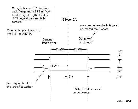
My last plan was to cut a single notch 4" wide on each side of the
S-Beam to allow clearance for the damper bolts. Then, weld a 1/2" x
1/8" x 9" piece of 4130 on the top of each side of the S-Beam to
stiffen what had been cut out.
I'll make sure the other Mark gets ahold of you - he's the one with
opinions on all the support systems.
Mark S
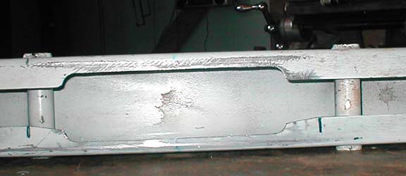
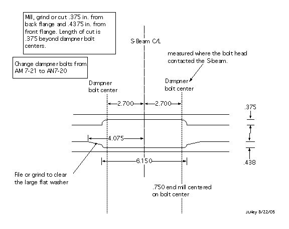
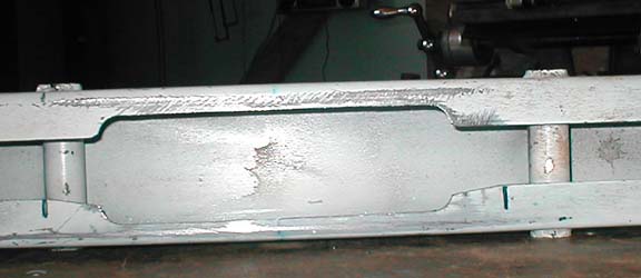
The slot needs to be longer as shown in Jerry's pictures and dwg.
Please hold off a bit until Jerry modifies one and tests it.
Paul
--
The Rotary Engine NewsLetter. Powered by Linux.
ACRE NL web site.
http://www.rotaryeng.net
Copyright 1998-2005 All world wide rights reserved.