Paul curious as to what your recommendation is. I'm planning on doing some
testing of a structure similar to an engine mount. I was going to try your
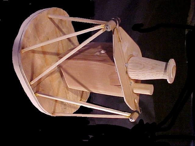
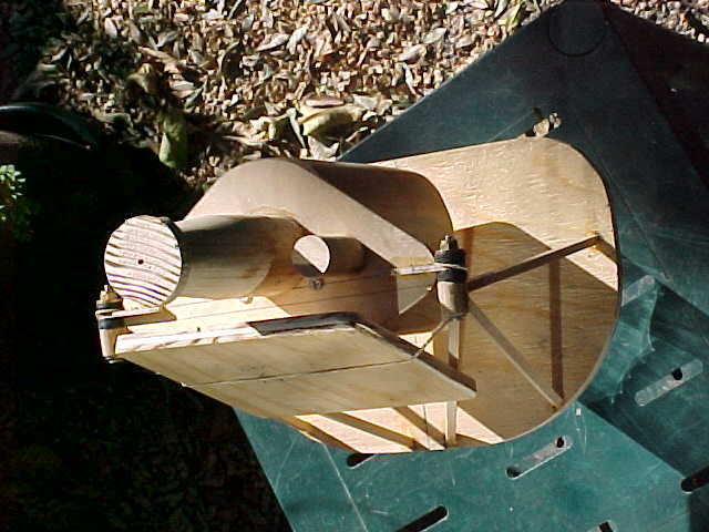
1/4 scale balsa model idea, but how do you scale the load? 1/4 of the actual
load seems much! Maybe there isn't a good way to do this?
Thanks
Jarrett Johnson
You don't really need to scale the load. It is just to find out
if the configuration is correct. In other words is each motor
mount point supported by a sufficient number of tubes. Namely three.
The trick is all tubes should be in pure tension and compression.
No tubes should have any bending loads on them at all.
Once you decide on a proper configuration the loads can be easily
be calculated. Or better yet you can use the actual motor mount and the fuse
as a lever to lift the front of your car off the ground.
Here is some stuff on this from the web site.
http://www.rotaryeng.net/mm-instruct.txt
Read this and then come back with questions.
There will be a quiz tomorrow morning :)
BTW the motor mount should be the last thing one designs.
First locate all major items that you are going to use
in your installation. Mufflers, turbos, radiator, intake manifolds
alternator, starter, etc., etc., etc.. Then design the motor mount.
You can use foam parts in a mock up. Or you can uses a good 3D
program like Rhino.
Paul Lamar
The Rotary Engine NewsLetter. Powered by Linux.
ACRE NL web site.
http://www.rotaryeng.net
Copyright 1998-2005 All world wide rights reserved.