Paul or anyone.
My airplane specs. have a wet wing (leading edge D section)
which
are
divided into main and auxiliary long range tanks. Total is
about
110
gallons. Holes are cut on both the middle bottom and front edge
of the
D
shape ribs to allow fuel to flow down to the pickup for the
mains
and
another pick-up and pipe plumbed to the auxiliary. That is
four
pipes
with
check valves, solenoids, side to side transfer pump for
balancing
the
plane
on the water. In addition the specs. call for pieces of rubber
to
be
fastened over the the ribs holes to prevent backflow during
turns.
The
rubber pieces are a joke. IMHO the design is less than
admirable.
There must be a better design approach such as installing
simple
flapper
valves like those that are used in hand fuel pumps or diving
snorkels?
I would like to eliminate the four tank concept and just make
the
whole
leading edge into one tank thus having only two tanks to deal
with. Any
foreseeable problems with this approach?
Thanks
Doug in Japan
Can you send me a sketch jpg showing all the parts? Fuel systems
are extremely important. Here is a picture of the metal flapper
valves
used
in the Lancair IV and ES I suspect. I think they yield a certain
redundancy in a slip or uncorrodinated turn situation. The last
thing
you want is an air bubble on the intake side of the high
pressure
pump.
The pump may fail to self prime when fuel is restored to the
intake.
Particularly if the pump has cavitated in the past. If it does
fail to
self prime it will rapidly over heat.
Paul Lamar
Paul,
It's not very clear from the picture, but these "Lancair flapper
valves"
are fabricated from a couple pieces of sheet aluminum riveted to
a
short
piece of piano hinge. They should be easy for anyone to make.
The
hinge pin should be longer than the hinge so it can be bent over
to
prevent it from sliding out. The "tab" at the top is to prevent
the
flapper from getting jammed in the open position. Once it is
bolted
into place, Lancair instructs the builder to put a bead of micro
around
the perimeter of the hole and then push the flapper up against
it
and
leave it to cure. After cure, you pop it loose and you now have
a
nice
sealing surface. Helps to put some packaging tape on the
flapper
before
pushing it into the micro.
Mark S.
Paul,
The system layout is identical to what you recommend ie: double
deck Andair
valve with fuel return to the tank it is drawing from. The
leading
edge is
divided into two tanks main inboard 38 gallons and aux. outboard
18
gals.
The D wing ribs go through the tank at regular intervals. Holes
are
cut into
the ribs to allow fuel to flow down towards the sump outlet and
vent out
along the top towards the wing tips. There are two pumps (one in
each wing)
that pump the fuel out of the auxiliary tank and downhill a few
inches and
back into the main tanks. Wings have a 3 degrees dihedral and
fuel
is drawn
from the bottom of the inboard side of the tank only. From there
to the
header tank is straight forward design and not a design concern
at
the
moment
In my case with an additional ferry tank in the aft luggage area
that
would mean 5 tanks to play with. It seems the logical solution
would be to
make the whole leading edge one tank. Thus I have only three
tanks
to deal
with.
Sloshing towards the wing tips can be handled with flapper valves
and but I
think finding a long fuel sensor over four feet long might be the
biggest
challenge.
Say I will be flying the C-150 to Portland and Seattle from Sept
12th
through the 19th if any of you rotary heads wouldn't mind me
stopping by for
a few hours.
Doug in Japan
I changed my mind about those Andair valves. They are in dire
need
of stronger detentes.
Header tank design is critical as is tank vent design.
Keep header tank tall and skinny.
EFI return flow to the header tanks is warm and full of bubbles.
Place the high pressure pump near the bottom of the header tank.
Improperly designed vents can empty a tank in minutes
at speeds over 150 MPH. Do not vent the tanks in such a way as to
pick
up dynamic pressure. Vent the header tank straight up and shield
it
from
air currents. Use vents with four small holes drilled 90 degrees
all away around the vent tubing. Place the main tank vents in a
unpressurized (static pressure) wing tip fairing. Place the
separate header
tank vent near the top of the fuselage straight up in an
unpressurized area.
Keep the bugs (literally) away.
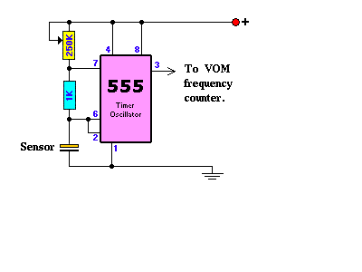
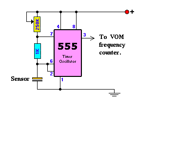
Fuel level sensors are easy to make. Concentric metal tubes open
on
both
ends form a capacitor with fuel as the dielectric. Hook this
capacitor
to a Radio Shack 555 IC oscillator and thence into a counter. As
the fuel
is burned off the capacitance changes and that changes the
frequency of the
555 oscillator hence the count also changes. Counters with LCD
can
be
cheaply cannibalized from low cost digital VOMs.
http://www.uoguelph.ca/~antoon/gadgets/555/555.html
Paul Lamar
Thanks Paul,
Good advise. I am afraid the SeaWind header tank vent design is
on
the
engine pylon facing forward, hence it might well pressurize the
header
tank. Not advisable.
The html location would not open but I am familiar with the 555
series in
timer applications. Hadn't thought to measure capacitance in that
way.
Clever.
How to keep the tubes separate? Plastic inserts?
Thanks
Doug in Japan
You make up a bunch of little Teflon spacers on a lathe.
Other types of plastic may or may not be compatible with
alcohol and gasoline.
Paul Lamar
Paul,
So how does 1/4" tube inside of 1/2" tube sound? I imagine the
Teflon
spacers need slots to allow fuel to travel between the two pipes
correct?
Doug in Japan
Correct on the slots os small holes. My guess is the diameters need
to be
closer.
What wall thickness for the half inch OD tube do you have in mind?
Paul Lamar
Paul
Still clue less on actual sizes. Probably better to look at sensors
already
out there. I have heard that if they much over 4 feet they are hard
to
calibrate. Guess it depends on size and material though.
Doug in Japan
There is a formula around for parallel plate capacitors with
an air dielectric. Also the dielectric constant for gasoline
and alcohol can be looked up on Google I suspect. The differnce is
what you are after. Here it is one example. Oil is 2 to 5
depending
on type. Here is the equation in jpg form.
If you place most of the sensor along the top of the tank and
gradually bend it down near the bottom or fuselage end of the tank
it will be more accurate where it counts. Namely near the end of the
fuel supply.
BTW the holes to pass fuel do not have to be in or just in the
plastic
spacers. They can be anywhere along the outer tube.
Paul Lamar
Jim Weir did an article on this in Kitplanes a while back. Look at
the
"Capacitive Fuel Gauge" articles.
http://www.rst-engr.com/kitplanes/
Scott Gettings
Yes he did but that is apples and oranges to what I am suggesting. He
used parallel flat plates for the capacitor so if there is any
dihedral
in the wings it will only measure the last half of the fuel supply
roughly.
Another big difference is the sophistication of the electronics. Use
of a 555 IC as a variable frequency oscillator is much much
simpler
than making an oscillator out of several op amps. The third
difference is
the use of a low cost digital frequency counter to indicate the
quantity of fuel. This is inherently much much higher resolution than
any analog gage such as Jim Weir used in his design.
Paul Lamar
Scott
Thanks for the intro to the web site. A lot of interesting info
there. I
thought of another way to make a inexpensive fuel sensor. It is based
on an
idea a group of my research buddies were commissioned to develop for a
Swiss
client about 23 years ago. Ready for this? It was a rubber duck that
when
placed in water would activate the circuit and then sqwuak when the
temperature got too hot. OK definitely not one our more challenging
projects
but we did develop a small sensor the activated when wetted. Perhaps
seven
of these epoxied into the tank would be good enough to indicate 1/8
of tank
increments.
Doug in Japan
Doug,
I would be interested in some of those sensors. Are they easy to
acquire. I am worried about identifying fuel levels in my Glasair, as
you stated earlier, it is difficult when you have one main take (the
leading edge of the wing) with a dihedral. Any help with these sensors
would be appreciated.
Barry Doublestein
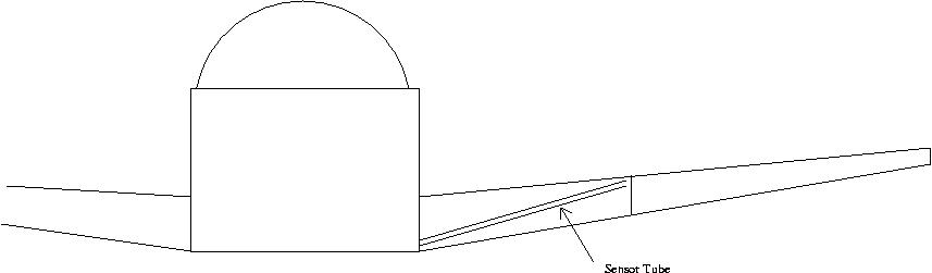
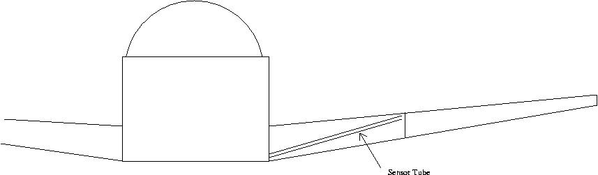
In the Glasair, is it possible to run a straight tube from the highest
point in the tank to the lowest? If yes, then the concentric plate
capacitor that Paul described will work.
In other words, run the tube at a diagonal through the tank, not vertical.
This is actually good electrically because there will be a larger change
in capacitance for a given change in fuel level, improving resolution.
See attached: fuel_sensor.jpg
Another idea is to use the parallel plate capacitors mounted to the end
walls of the tanks. One inboard and one outboard. Both the outer and the
inner are submerged when the tank is full. Only the inner one is
submerged when low fuel. Wire them in parallel.
Both of these approaches require some linearizing scheme so that full on
the guage is full in the tank, half is half, and empty is empty.
Actually, ANY level indicator system for a tank that doesn't have a
constant cross sectional area in the horizontal plane requires a
linearizing scheme.
And, actually, a curved, concentric tube would work, though would be
harder to build.
Matt-
Nothing could be easier or cheaper :)
Paul Lamar
The Rotary Engine NewsLetter. Powered by Linux.
ACRE NL web site.
http://www.rotaryeng.net
Copyright 1998-2005 All world wide rights reserved.