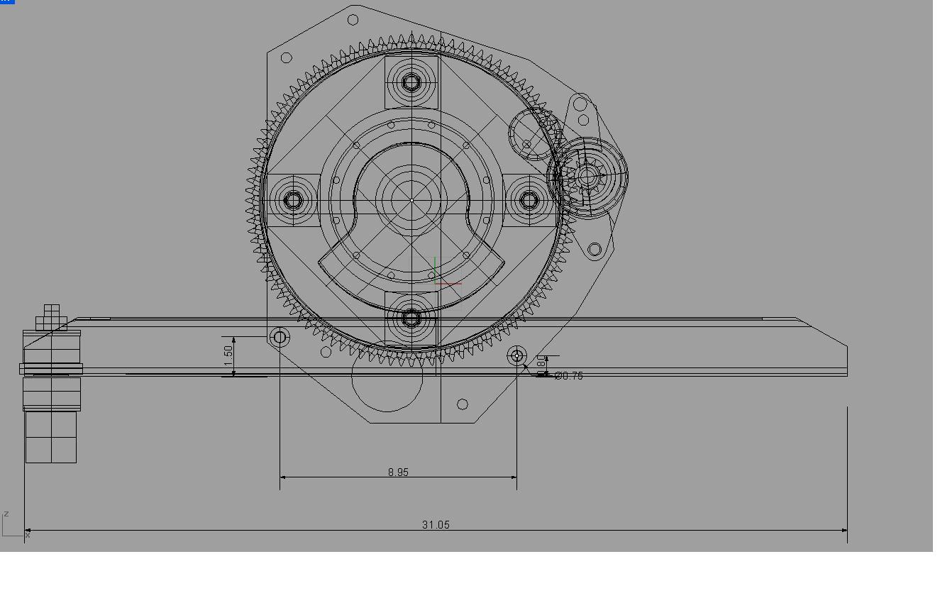
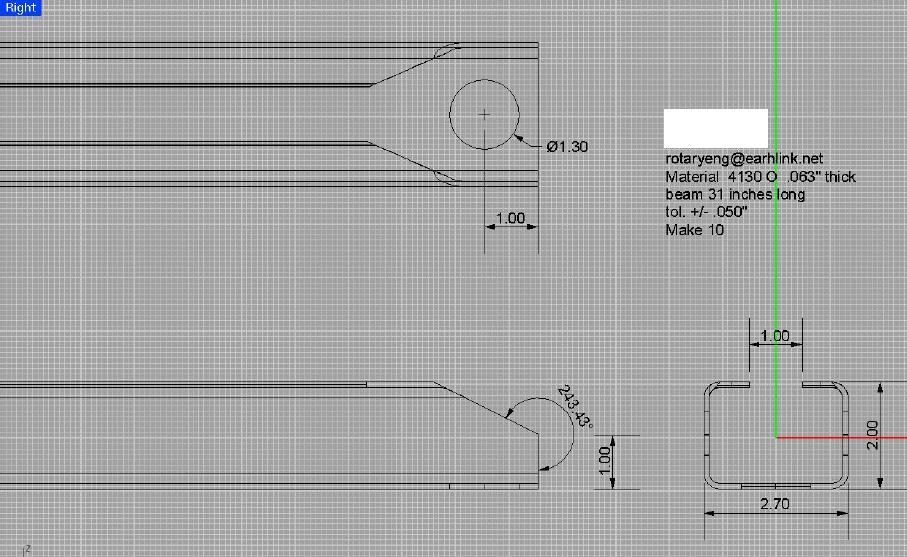
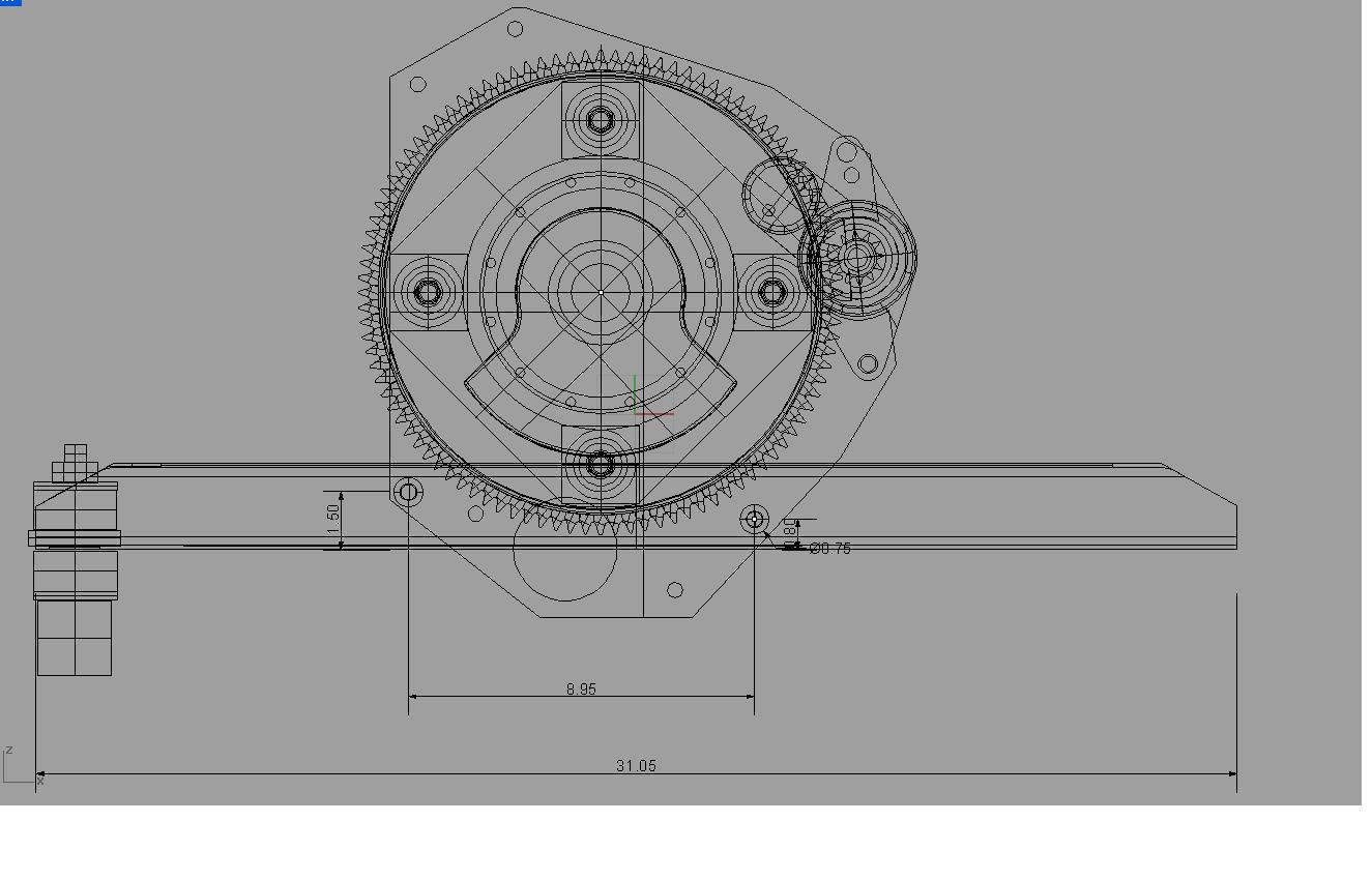
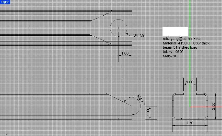
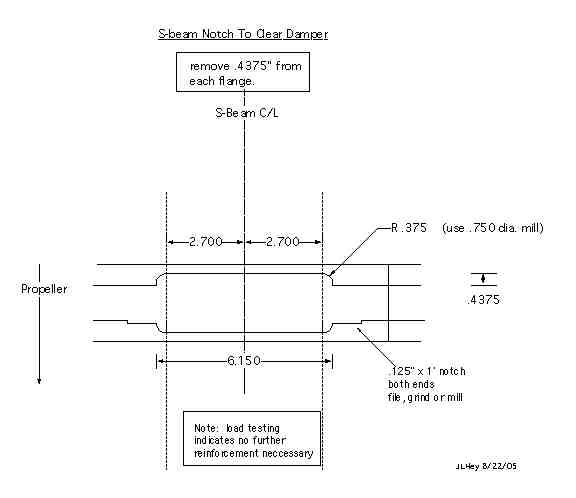
If you give me all the dimensions, the material, support locations, and the
load location(s) I'll do the FEA on the beam, if you like.
Bill Dube'
At 02:43 PM 8/31/2005, you wrote:
Paul, I did the static load test on the S-beam today. I tested two S-
beams using identical loads of 1700 lbs. I got this figure by
weighing just the front end of my truck on a commercial scale. The
total came to 3400 lbs. So one wheel should be 1700 lbs.
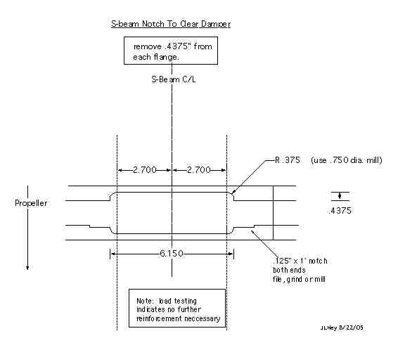
Both S-beams were fully notched to clear the dampner . One beam
had the reinforcing strips which in this case were .5"x .125" x 12"
304 SS. This beam was somewhat arched (low in the center) by the
welding. It is a junk beam and I did not feel the need to build a
fixture to hold it straight while welding. Also, it was welded in
one long pass on each side which is guaranteed to produce some
distortion. With a fixture and alternating short welds, there would
be no distortion.
The beams were stretched across small pieces of 1 x 3 plank at either
end and the truck wheel was lowered on to the center of the beam
using the fixture you designed to put the weight on the bolts. We
used mechanics clay to measure the amount the beams sagged under the
weight. I wish I had taken a picture but you can get the idea.
The reinforced beam sagged exactly .063 under the weight of the
truck. The beam without reinforcement sagged somewhat more at .145
inches. Both beams returned to their original shapes when the
weight was removed.
I am looking forward to your interpretation of these numbers. In
particular I am very happy with the performance of the unreinforced
beam as it seemed to be more than strong enough for our purposes.
That is just me guessing, of course. The last photo shows exactly
how the finished notch looks. There is plenty of material left on
both of the top flanges. Jerry
The deflection is of no consequence unless the beam does not
return to its original shape. 1700 pounds is a severe test and
only likely to occur if the airplane is drooped in from ten feet
or so. Also a 6G pull up where something else is likely to fail
first.
Great work. Looks like we over did it a bit on the reinforcement:)
Thanks again Jerry for all your help. Motor mounts
are one of the key items to make a successful rotary engine installation.
Paul Lamar
If you give me all the dimensions, the material, support locations, and the
load location(s) I'll do the FEA on the beam, if you like.
Bill Dube'
Thanks Bill. Looking forward to seeing the results.
Paul Lamar
--
The Rotary Engine NewsLetter. Powered by Linux.
ACRE NL web site.
http://www.rotaryeng.net
Copyright 1998-2005 All world wide rights reserved.