From the pictures and my limited engineering education: I would
say the "stress" and "safety" pictures are very significant also. They
show the "points" that the steel comes closest to reaching its limits
and these points could be beefed up with thicker layers. Where as the
"deflection" picture shows where the shape (cross section) of the beam
could be beefed up.
I think about the "rule of thumb" 50 diameter : 1 wall thickness
for tubing. Think of the beam as a tube. For bending the best possible
use of more metal is to increase the diameter of the tube. While for
those localized stressed areas thicken the wall.
I looks like adding a tie to the top of the beam on the ends and
reinforcing the mounting holes would reduce the stress around the
holes and stiffen the beam the most.
Of course after differential equations and thermodynamics I
drooped out of mechanical engineering and went into computer science.
So my opinion doesn't mean much.
Blake
The stress and deflections around the large holes on the ends
are probably inaccurate as the beam is supported by rubber bushings
that tend to spread the load. Very difficult to model that situation
and probably not worth the effort. Minor permanent distortion there would
be of little consequence.
If you look at the pictures carefully, you will notice that I put
rubber mounts on the ends. These are, indeed, spreading out the load. If I
had not, the model would have shown very severe stress concentrations at
the mount holes. This would have resulted in an unrealistic (and useless)
simulation.
As it is, the area around these holes is more stressed than I
would consider safe. This may be because the holes are large and a
significant fraction of the metal is absent. I would weld in a thin washer
doubler.
Better yet, use 0.090" wall rectangular tube instead of 0.063"
wall. The construction would be much simpler. No scabs or stiffeners
needed. Not much additional weight. Present 0.063" wall beam weighs about 4
lbs. A 0.090" beam would weigh about 5.8 lbs.
I'll run it with 0.090" wall just to see what happens.
Bill Dube'
See my previous message on the 1/2 inch thick alloy plate on
the ends.
We got a lot of beams made up we would like to use.
Where is the plate? It is not in the drawings.
Bill Dube'
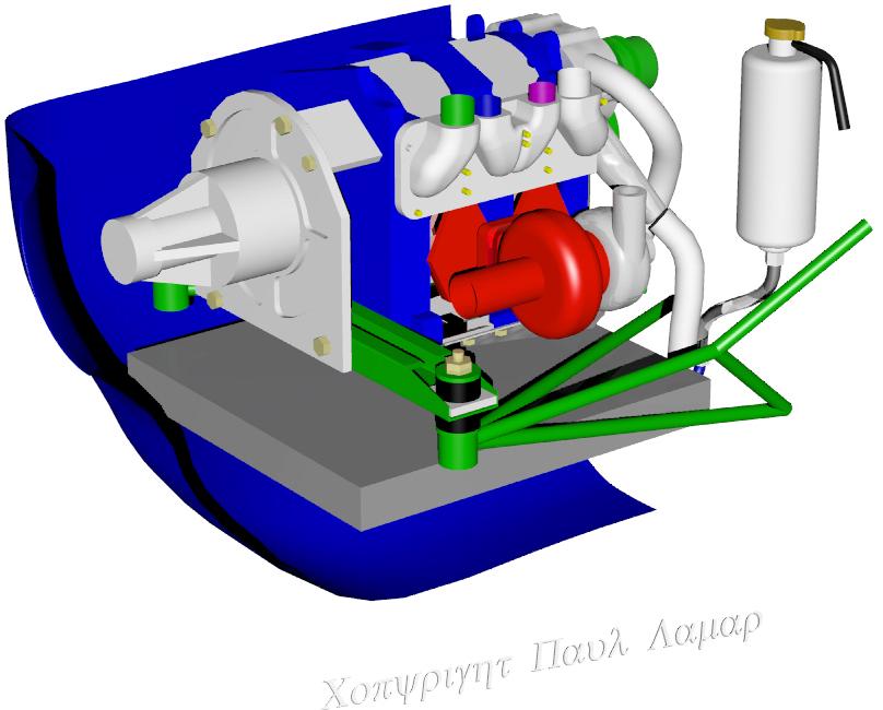
OK here are some 3D's and pics showing it. We have had them for so long
I kind of take them for granted. They are necessary to take the
radial thrust loads from the rubber bushings. They have been an
integral part of all the motor mounts since the day we decided to copy
the Questair Venture style of motor mount. The last pic is the original
Bill Schertz design.
Paul Lamar
The Rotary Engine NewsLetter. Powered by Linux.
ACRE NL web site.
http://www.rotaryeng.net
Copyright 1998-2005 All world wide rights reserved.