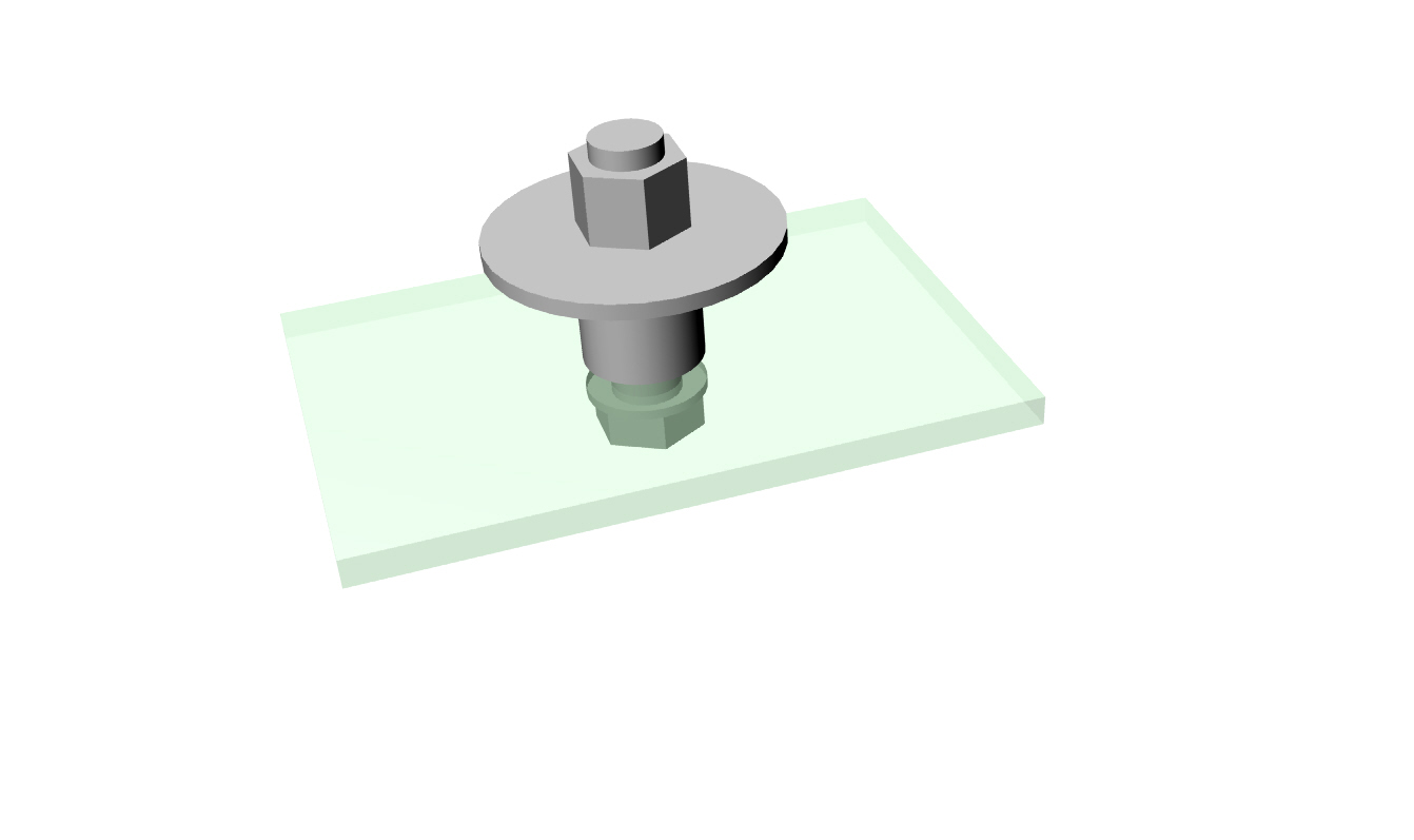
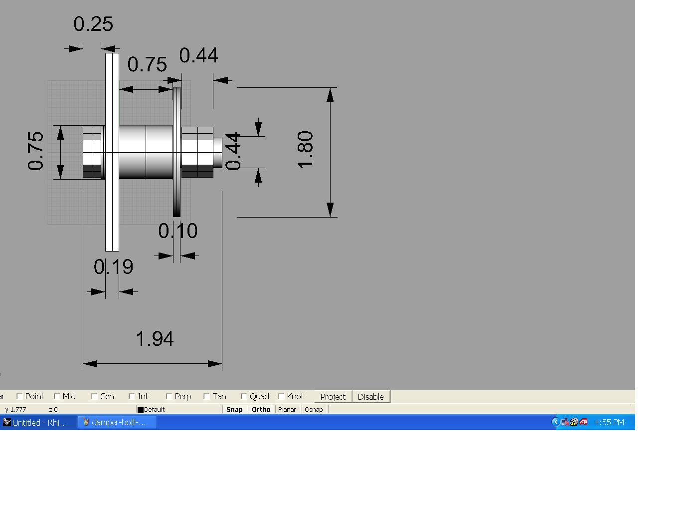
>
> Paul-
>
> Just FYI, we found a local machinist to perform the mods. He has
> finished re milling the S-Beam & I will be picking it up tonight to
> perform a test-fit. If it works, I will return it to him to get the
> key stock welded on.
>
> He's having some sort of problem re milling the aluminum mounting
> plate -
> he thinks the starter dimensions on your CAD differs from the
> dimensions
> for the existing starter hole. I'll try to get it straightened out
> tonight when I get the S-beam, otherwise he wants to wait until I
> have a
> starter in-hand to compare against.
>
> Mark & Mark
>
> Good idea. There seems to be a lot of slightly different starters
> floating around. Best to have the actual one you are going to use.
>
> Paul Lamar
Mark, weld the key stock from the center outward. With every stitch
weld the key stock will shrink slightly lengthwise. If the ends are
welded first, the ends of the beam will be pulled upward by the
contracting key stock. This would not present a problem on new engine
mount construction, but changing beam end locations on a completed
mount might make it difficult to reassemble, On my next one, I will
keep the stitches shorter, around .375 inches and at least one inch
apart. But the main thing is to start in middle and work toward the
ends. Jerry
Thanks for the tip, Jerry - I will pass it along to the machinist.
Fortunately, he insisted I test-fit the part after milling before he
welded on the keystock. I have discovered that my S-Beam still suffers
interference after milling. I tried bolts both per-Tracy, and reversed
& they still hit one side or the other.
The CAD drawing was ambiguous on which side was which. I had him mill
the angled sides on the redrive side of the S-Beam, since the purpose of
the angles was to clear the wide washers on the damper plate.
In any case, it will have to be milled further. My question is whether
the bolts are supposed to be reversed or not. If so, then the milling
must be done on the already narrow side -- I am concerned that milling
this side further will result in the keystock being wider than the
remaining width of S-beam top. On the other hand, if the bolts are to
be reversed, then the milling is done on the (wider) engine side. It
appears that this would result in a symmetric amount of material being
removed (both sides would have the same resulting top width). If this
is the case, then I will have him mill out the same angled shape as on
the redrive side -- I do not see any reason the shapes of the milled
sides cannot be the same.
No question now that I am not moving forward on cutting the mounting
plate for a new starter hole until I have a starter in-hand. We're not
quite at the point of interchangeable parts with all this.
mrs
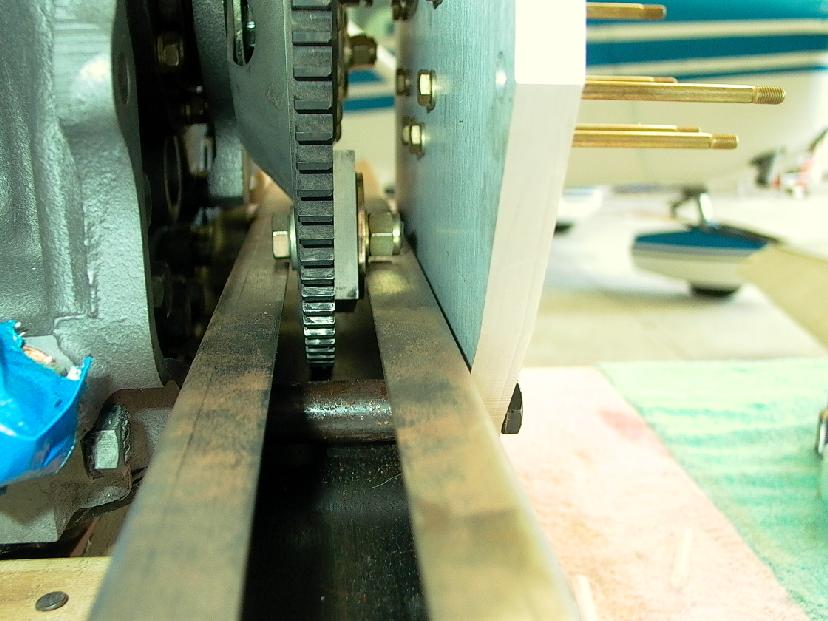
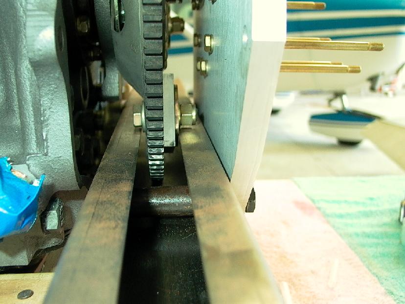
Got any pictures Mark? Should not matter which way the bolts go.
You could also shorten them and use shear nuts. Or better yet.
low shear castle nuts with cotter pins. AN320-7 in the 2004-2005 Aircraft
Spruce cat. Page 86. The over all height of this nut is .219 instead of about
.5 for the Nylocs. Furthermore one or two threads must protrude
from the top of the Nylocs to be safe. Not necessary with a castle nut
and cotter pin.
Cut down the bolts you have about a 1/4 inch
and drill them for the cotter pins. That will save about 1/4 inch in
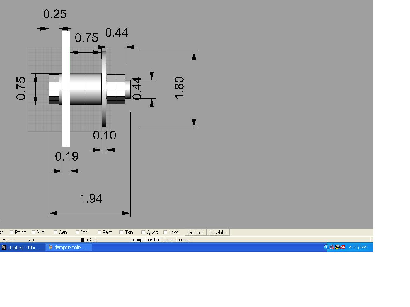
length. The bolts tracy supplied for my PSRU appear to be AN7-14 with
an overall length under the head of about 1.6 inches. .6 inches
of that is threaded portion. .25 off that should give you plenty
of room for a castle nut and cotter pin. Namely about .35 inches.
The 1/2 inch high Nylocs supplied by Tracy are marginal from a heat
point of view anyway.
The shorter bolts and lighter weight nuts will reduce the cantilever
loads on the metal spacers due to centrifugal forces.
Bill Dube, if you don't mind could you do a FEA of this config?
There has always been a question in the back of my mind about
just how viable this torque damper scheme really is. It seems
to be working for hundreads of hours so far on several airplanes.
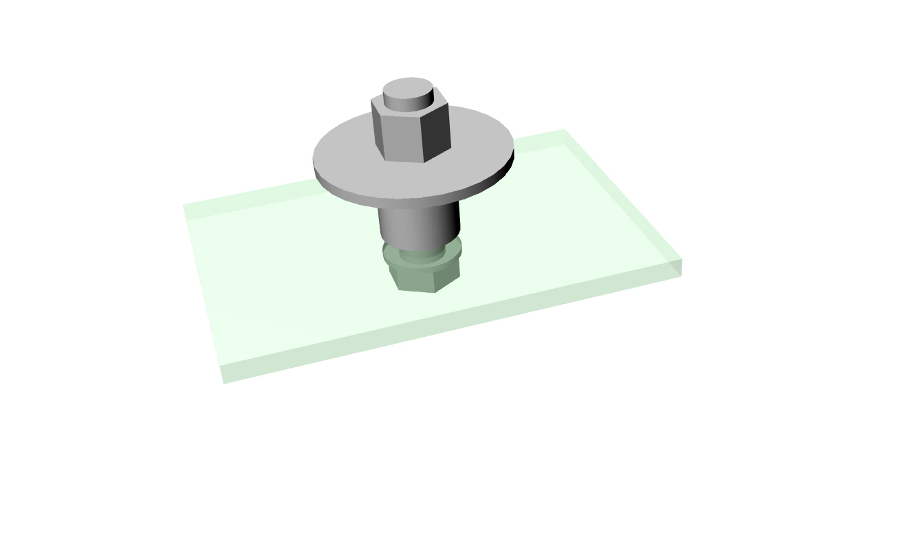
Volme of the parts in cubic inches is:
Large washer ---- .24227
nut-------------- .13924
shank of the bolt .25368
head of the bolt .07956
little washer --- .01821
Parts are on a 4 3/8 inch radius whirling at 8000 RPM.
The flat sheet metal is the flex plate assumed to be 3/16 inch thick
steel for now. There is a simultanous side load applied to the center of the
spacers of about 160 ft pounds of torqe divided by four
spacers and rubber bushings.
Paul Lamar
The Rotary Engine NewsLetter. Powered by Linux.
ACRE NL web site.
http://www.rotaryeng.net
Copyright 1998-2005 All world wide rights reserved.