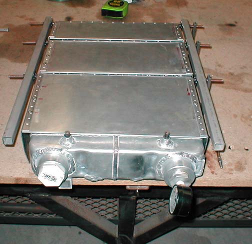
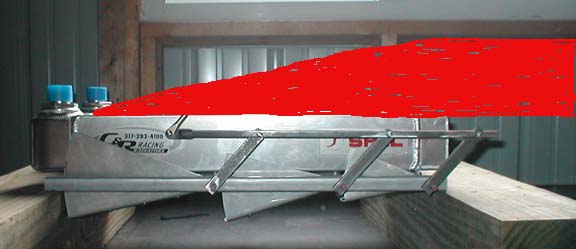
Ok, so I know this subject has been beaten to death many times.
However, I'd like to bring it back to life again, just to get
current-thinking vs. what we've gone round & round about in the
past.
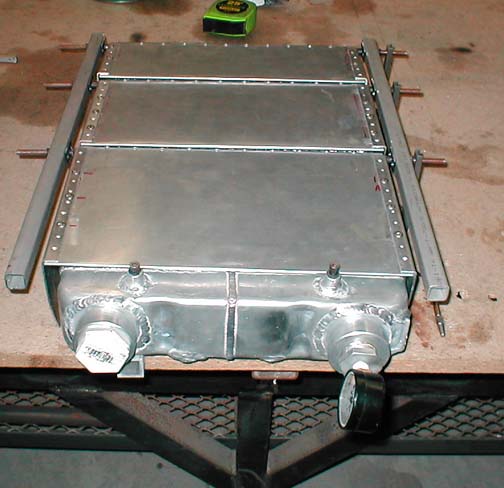
It's time for me to start buying radiators/coolers for our M2 build.
What are the current best-bet parts to be considered? Mazda
original
equipment, vs aftermarket? Are we still all convinced that pivoting
a
radiator off the s-beam & hanging it below the cowling is the best
way
to shed heat? On the oil cooler front, I see that Jerry's latest
scheme is to mount it behind the engine & bring cooling air
straight
down the firewall. Given that the air will have been heated by the
engine / exhaust manifold on it's way there, I wonder whether the
delta-T in this configuration will be sufficient to provide the
proper
cooling.
On the more mundane side, what are good sites to order hoses & what
not
from? Paul, how about the clamps you believe are must-haves?
As you can see, we're transitioning from "get the engine built"
thinking
to "get the engine installed" mode. Heck, it's been a whole 3 days
since I last exercised the credit-card for airplane parts.. wouldn't
want
it to go stale or anything... ;-)
Mark & Mark
Mark, I have recently updated the "How to Cool your Wankel" so that
is my position on the subject.
http://www.rotaryeng.net/how-to-cool12.html
If you have any questions please let me know as I am getting ready
to publish it in book form.
Have you taken a look at lulu.com <http://lulu.com> Paul? It is a
publish-on-demand service which is free to the author. They print up a
book when an order is received. I think they take a 20% cut on each
book, and return 80% to the author. Could be wrong tho.
Mark & Mark
The silicon hose and constant torque clamps can be had from McMaster
Carr.
Thanks for the tip Mark. I was going to go with a friend in Florida but
I
will
look into it. I am a control freak so I was going to call out
everything,
paper stock, format, binding etc. etc. In my experience with a couple
of books in the past they tend to sell for years. I wrote a chapter or
two
in How to Hot Rod Volkswagen Engines 30 years ago and it is still
selling
:)
Paul Lamar
Paul,
I'm just getting to the point of thinking about firewall forward
components.
I plan on putting the Renesis in my RV-8. Current thought is to get the
mount from Creative Concepts, the alternate rotary cowling from James
Aircraft, the control unit from Tracy Crook and the engine built by Bruce
Terrentine.
Since I'm new to the ring, I'm sure there have been lots of discussions
on
which components to use. Is there somewhere I can go to get info like
the
size of the heat exchanger I need? Which components are others using?
How
have other RV-8 builders installed & ducted? I have the same type
questions
for the oil cooler too. It sounds like the stock cooler is the right
choice, but has anyone ducted it all under James's cowling?
I ordered the finishing kit last week, and will probably start ordering
firewall forward parts before the year is out.
Thanks,
Chris Mallory
Most people use the stock 2nd gen oil cooler. You will need about
a 600 cubic inch rad. Available from many car racing radiator sources.
The first thing you need to do is either construct
a full size detailed mock up or do a 3D of the proposed layout. This
will save you a year and the time making parts over again. I can do that
for free if you wish. That will determine the dimensions of the rad
within the
600 cubic inch parameter. IMHO you will save lots of money and get a
better
motor mount from Jerry Hey. I have the dimensions of the Will James
cowl so I can fit everything in. Here are three RV8 3D's that will give
you some ideas. None of these meet all the ideal criteria in
http://www.rotaryeng.net/cooling.html but they are close.
Namely:
A. Feed cold air only to the rad.
B. Makes sure there is nothing behind the rad to impeded the air flow.
C. Make sure the back side of the rad is shielded from the exhaust.
D. Make sure the rad duct is the proper shape.
Once you make a decision on the exact configuration stick to it come hell
or high
water as that will minimize the time required to get it finished.
Paul Lamar
I forgot to mention the the intake manifold. The exact layout you choose
depends on what intake manifold you have. As far as I know there is
no off the shelf manifold for the RX8 engine. That means you will
have to make one. Tom Webber is making slide throttle parts and Jim
Poole is boring rotor housings for peripheral ports. That makes a p-port
RX8 engine about the most powerful normally aspirated rotary there is
other than a 3 rotor of course. It is also about the easiest manifold
to make as there are only two runners rather than six.
The last decision is what kind of muffler you want to go with.
Paul Lamar
I tried to go to j-winddesigns.com, and it is gone. Do you have the new
address so I can check out his engine mount?
Maybe I'm thick headed, and I'm sure I'm about to prove the old addage
"Better to be quiet and thought a fool than to open your mouth and remove
all doubt" but here goes anyway:
I read through the cooling page on the ring. (Very informative by the way)
but am confused why a larger thin heat exchanger is better than a small
thick one. If the idea is to slow air flow in front, then speed it up
behind, the thick exchanger wouldn't be as big a liability? What am I
missing?
Chris
Your right. Dang Jerry did you not pay your web site bill? :)
If Jerry does not fix his web site I have plenty of pictures of his
product.
The rate of heat transfer is directly proportional to the difference
in temperature between the cooling air flowing through the rad and the
metal
the rad is made from.
With a thick rad the cooling air gets warmer as it flows through the
rad. Therefore the rule of thumb is the first half of the rad does
3/4 of the work and the second half does 1/4.
The second factor is the drag on the cooling air. That is manifest
in a pressure loss. You start with dynamic pressure which is the pressure
you get on a flat plate held perpendicular to the air stream.
The rad looks like a porous flat plate to the air flow. Therefore
the amount of drag you get from a rad is a function of it porosity.
Highly porous thin rads slow the air less than a less porous thick
rad. Always think of the limits. One limit is a non porous metal
plate. High drag. The other limit is no plate at all. No drag.
Consequently you want the least porous rad that still does the
cooling required. A thinner rad is more porous than a thick rad.
The ideal heat exchanger would be infinitely thin
with infinite frontal area.
Another factor is the drag of the heat exchanger acting
on the air flow is proportional to the square of the velocity.
If we can slow the air to half it's forward speed before it flows
through the rad the drag on that air will be 1/4 as much.
How do we slow the air and keep the air volume per unit time the same?
We use a device called a diffuser. Diffuser presents a small hole
to the air stream at the front of the airplane and gradually transitions
to a large hole where the rad is attached. The air speed changes from
high to low in the bargain. A second goal of the diffuser is
to make sure the air velocity flowing through the rad is
uniform all over the width and height of the rad.
Therein lies all the R & D done on this subject by Kuchemann & Weber
and Kays & London. Kays & London came up with the best diffuser
for our purposes. A simple wedge. You might say yes but... the air
is forced to make a sharp turn. True but it is just a lucky set
of circumstance that the air turbulence inside the heat exchanger
enhances the transfer of heat from the metal to the air.
The sharp turn enhances the air turbulence.
Now the jury is still out on whether a K&W diffuser is less
drag than K & L diffuser. I am willing to bet you would have a
tough time measuring the drag difference between the two optimized
systems.
Paul Lamar
Paul,
Per the 3D illustration in your cooling article of the K & L wedge diffuser
feeding the horizontal exchanger... What is the drag penalty of dumping the
low pressure outflow from the heat exchanger through the louvers into the
high pressure free stream air below the cowl?
Michael White
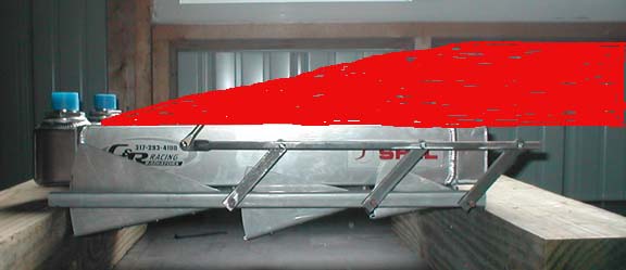
They are fundamentally no different than almost any other cowl flap.
Cowl flaps are widely used on radial engines in a 360 degree curved form.
In this case they are on the flat bottom of the cowl.
Drag I am sure depends on how open the flaps are. They are variable venetian blind
type flaps. At max climb angle when max cooling and wide open cowl flaps are required
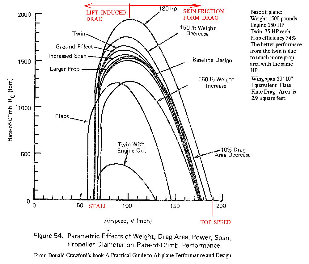
aerodynamic drag has little or nothing to do with the climb rate. Climb rate has
mostly to do with the power to weight ratio of the airplane. Drag as a factor is down
in the noise. See the enclosed chart from Donald Crawford's book A Practical Guide to
Airplane Performance and Design. The main reason is the dynamic pressure is
low due to the climb speed. Drag is proportional to velocity squared. Over all drag
is 25% of what it is at 200 MPH.
At cruise the relative velocity of the air coming out is not high. It is more of a
suction operation rather than a blowing operation. The cowl flaps are nearly closed
and the air flow angle is 25 degrees or less to the free stream flow. Probably less.
It might even energize the boundary layer in some configuration reducing the drag
and not increasing it. However no data pro or con so far.
There really is no other viable choice for a incorporating a
modern, large area, thin heat exchanger under the cowl. If there is something I am
missing I am not aware of it. I am open to scale 3D drawings of such a
configuration however.
Thanks for bringing this subject up. I need to add something about it in the
book.
Paul Lamar
The Rotary Engine NewsLetter. Powered by Linux.
ACRE NL web site.
http://www.rotaryeng.net
Copyright 1998-2005 All world wide rights reserved.