Speaking of the S-Beam, a word of caution & a question.
On the caution front, I tore down the S-Beam to bead-blast it before
priming & discovered significant amounts of cutting fluid wicked beneath
the mounting blocks. My presumption is that the local rework of the
SBeam is the source of this fluid. In any case, I'm sure it would not
have done good things for the rubber Barry mounts if not caught &
cleaned up. Folks who are getting this rework done for them should
either remove the mounting blocks beforehand themselves, or check
afterward.
On the question side -- I did not pay enough attention when tearing down
the SBeam. I cannot remember whether the rubber mounts are installed
male-side up from the bottom, or male side down from the top.
Logically, it seems like male-side up from the bottom makes the most
sense. Jerry/Paul -- which way is right??
Mark
Male side up sounds right.
Paul Lamar
We spent most of the day working on the M2, and have run into a few more
issues. The other Mark will be posting volumes of photos & details, but
here is a summary of what we've run into so far:
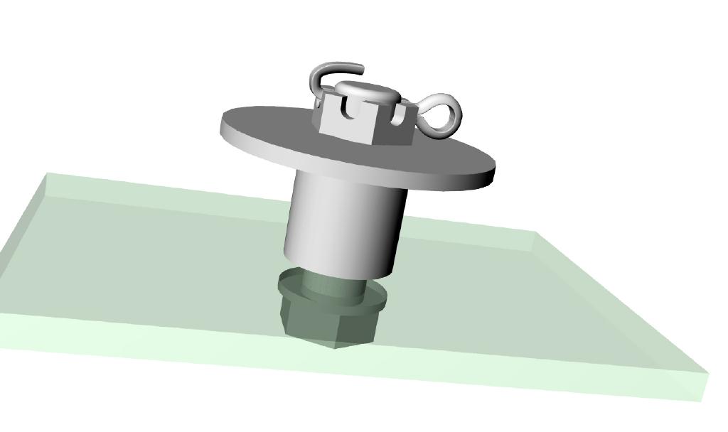
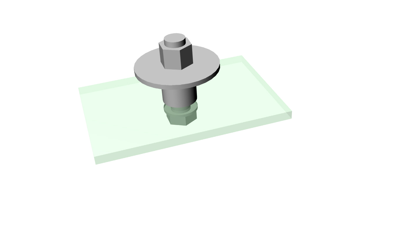
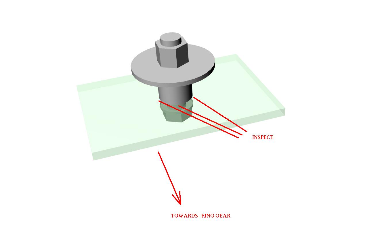
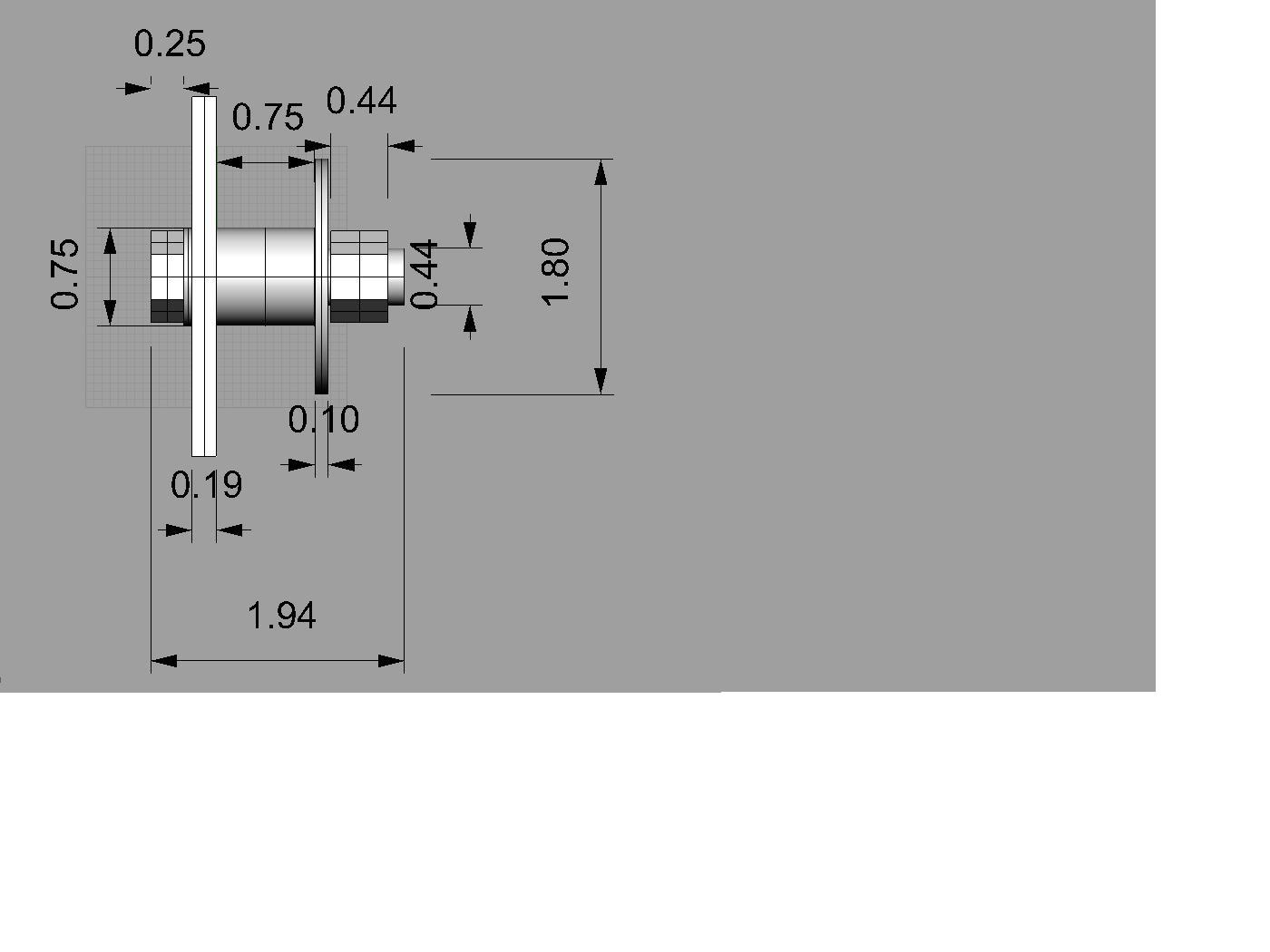
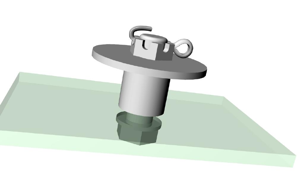
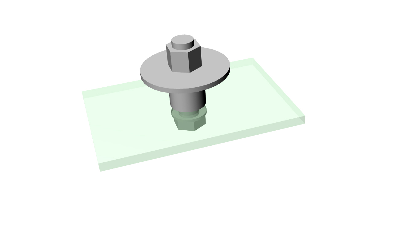
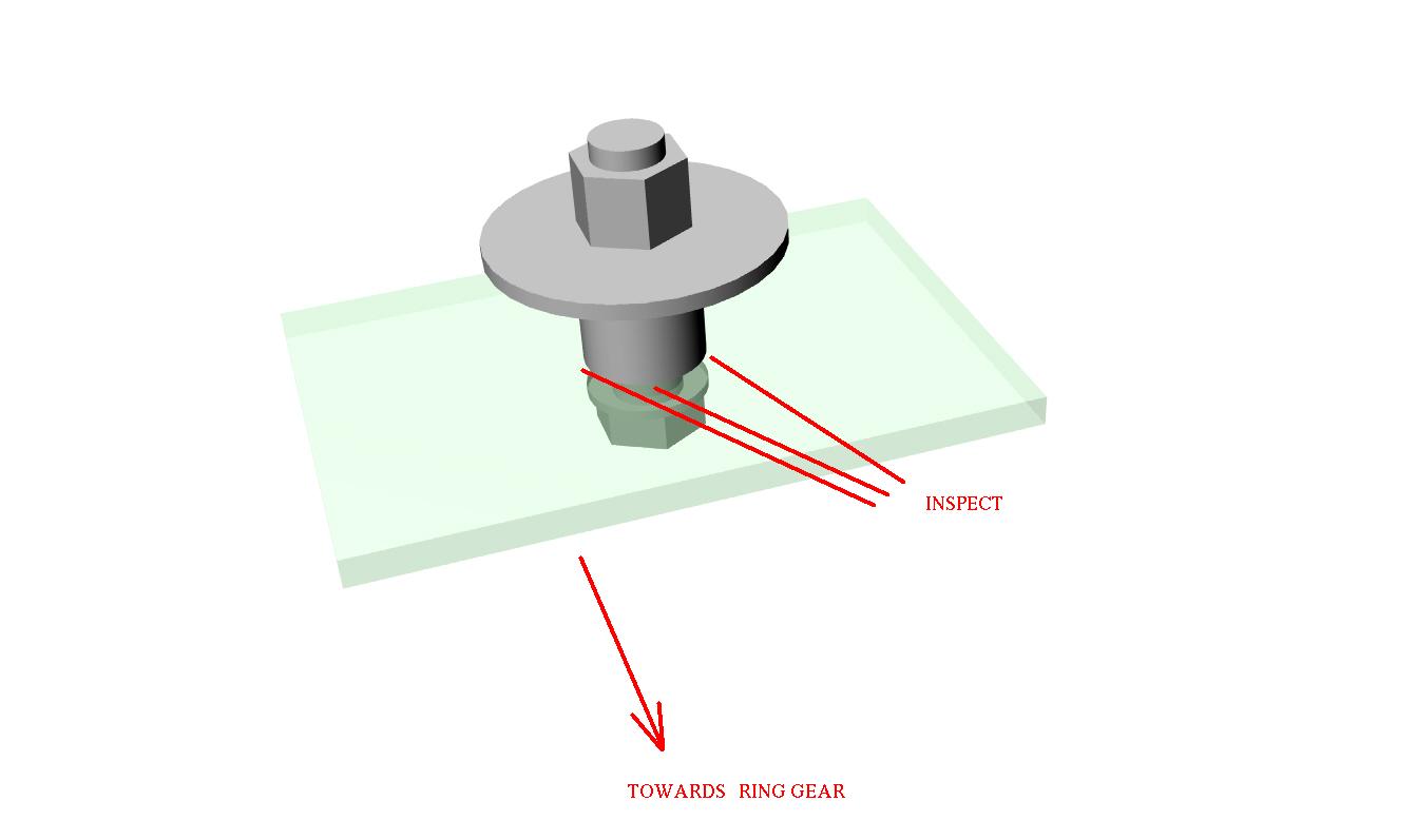
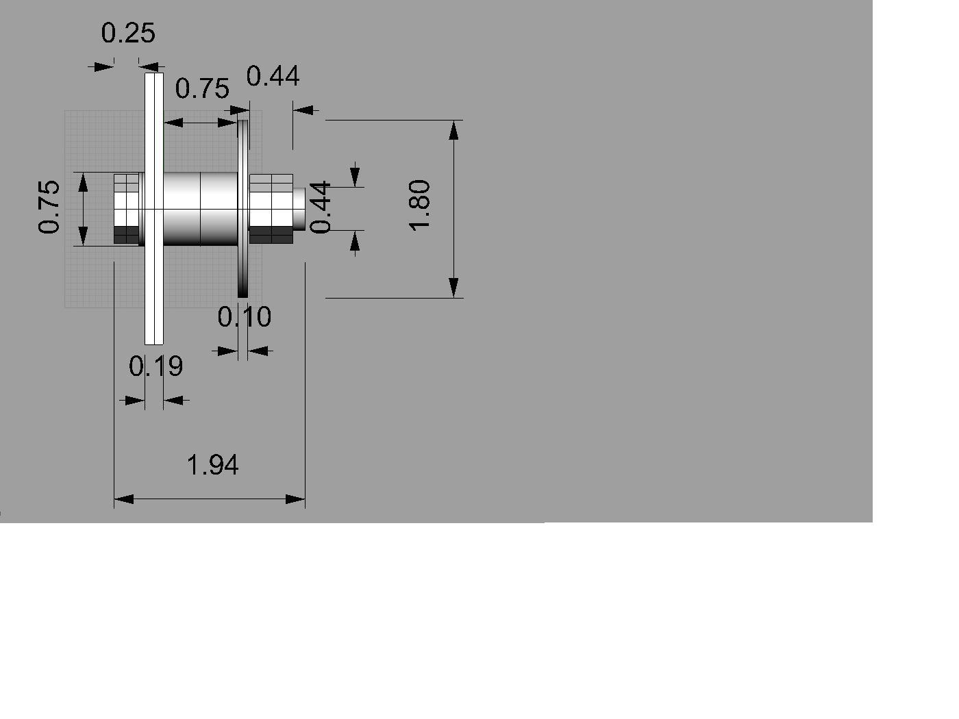
1) AN7-13 bolts will not work as replacements for the AN7-14 bolts Tracy
ships with the RD-1C standard. On my SBeam, the bolts must be inserted
opposite the direction Tracy specs. The AN7-14 bolts from Tracy have a
shank which is just
*barely* long enough when reversed to penetrate
completely through the damper and flex plate. About 1/2 thread extra.
The AN7-13 bolt shanks do not fully penetrate the flex plate -- about
1.5 threads inside the flex plate. Since these bolts carry 100% of the
HP from the engine to the prop via the flex plate holes, I do not
believe it is safe / acceptable to use these bolts. I am having the
original AN7-14 bolts milled down to AN7-13 length + 2 threads. I am
also going to drill holes in these milled bolts 2 threads forward of
standard position. This will result in castle nuts exactly fitting the
bolt with 1 thread showing and the holes in optimal position. This will
give me 1/16" clearance of the SBeam.
2) Mounting the engine puts us within 1/4" of where we wanted to be from
firewall to front of prop flange -- great! We saw the Sbeam flex under
the weight of the engine as we lowered the engine hoist. We measured
the deflection and it was an even 1-degree on each side of the beam. We
presume this is acceptable.
3) The VAM muffler
*almost* fit. The exhaust pipe hits one of the mount
tubes, preventing the exhaust manifold flange from seating against the
engine correctly. There seem to be 3 possible solutions:
A) Make an insert for the manifold flange which adds appx 1/4". Not
convinced the bolts are long enough for this.
B) Cut the exhaust manifold pipes & lengthen them so the VAM moves
1/4" - 3/8" farther away.
C) Cut the VAM exhaust tube & increase the angle toward aft so it
clears tube.
4) We borrowed a standard M2 cowling & test fit it. Acres of space
inside, except the SBeam forward (vertical) tubes interfere with the
bottom of the bottom cowl. We are concerned by this, since we expected
to require a custom cowl. It was amazing how close the standard cowl
came to fitting.
More details and photos coming.
Mark & Mark
Correct. You need to shorten the AN7-14 bolts.
You need plain shank inside those washers.
I covered that already I think.
But hold off till tomorrow.
I need to makes some stress calculations on those castle nuts.
More on this and the rest of the message later.
I need to pick up Robin at the airport.
Paul Lamar
The Rotary Engine NewsLetter. Powered by Linux.
ACRE NL web site.
http://www.rotaryeng.net
Copyright 1998-2005 All world wide rights reserved.