Hi Paul-
We got the parts back from the machinist & went
out to try a test-fit.
There is one new issue I want to get some feedback on.
Relocating the starter to the 9-oclock / 3-oclock
position per your
CADdrawing has resulted in one of the engine mount
bolts being
covered by
the body of the starter. It is the bolt
immediately above the
starboardS-Beam mounting bolt. (The bolt which
does not go into a
tapped hole on
the block).
After pondering a variety of solutions, we've come
to the
conclusion to
simply eliminate that bolt. Looking at the bolt
pattern on the other
side of the engine, we see a bolt to bolt distance
which is even
greaterthan the distance created by leaving out
the bolt we
propose. Also --
since this bolt does not go into a threaded hole
on the block, we
do not
believe it adds much in the way of stiffness to
the mount connection.
Finally -- even if we were to use the bolt, we
could not get a spacer
behind it, since the bolt for the starter motor is
very close near by,
as well as the starter cover. Net result -- the
spacer would
interferewith properly mounting the starter.
If we must use this bolt, our plan would be to
mill out a pocket in
thestarter body for the bolt head to fit into. We
believe this is
do-able.
Comments? (No, I didn't bring my digital camera
-- thus no pics)
Mark & Mark
The trick is to use that bolt to mount the starter
and then drill
a hole in the starter flange for the bolt above
it. Al Gietzen
came up with this great idea. Here is a picture of
his set
up.
Paul Lamar
Any comments regarding the pros and cons of having
the motor mounts in the horizontal instead of
vertical position in this installation?
Scott Gettings
The main vibration generator what there is of it is torsional from
the engine firing. Twice per rev so you want the soft motor mount
in the axial (Horizontal) direction. Vertical would be in the radial direction.
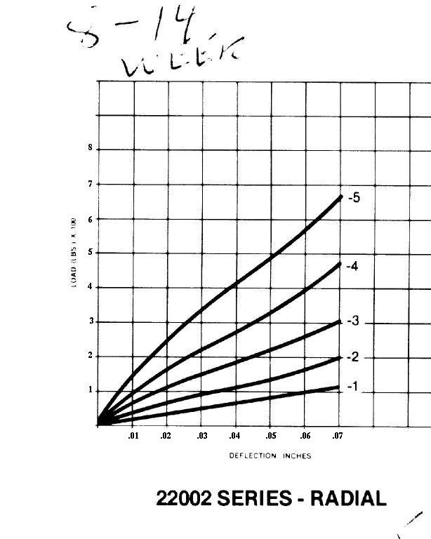
Here are the stiffness curves for the Barry rubber bushings.
Paul Lamar
Correction.
Here is the correct radial deflection chart.
When I scanned it in the first time the x axis and y axis numbers were
near impossible to read so I replaced them using xpaint.
I got the x axis numbers wrong on the radial chart.
It is .01 .02 .03 etc etc instead of .1 .2 .3 etc etc.
Big diff.
Paul Lamar
--
The Rotary Engine NewsLetter. Powered by Linux.
ACRE NL web site.
http://www.rotaryeng.net
Copyright 1998-2005 All world wide rights reserved.