Paul-
Here are the photos I was referring to earlier.
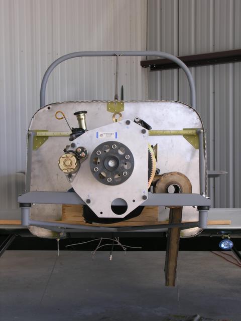
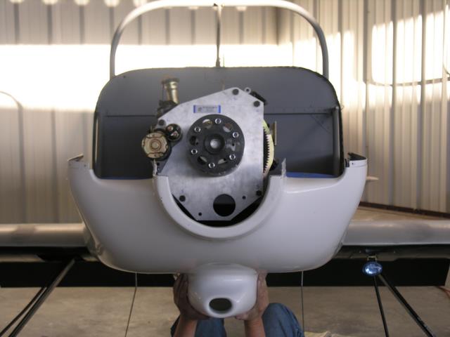
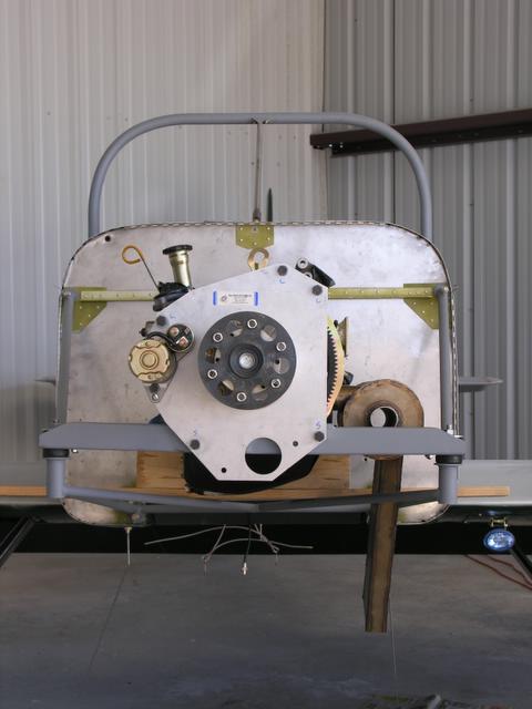
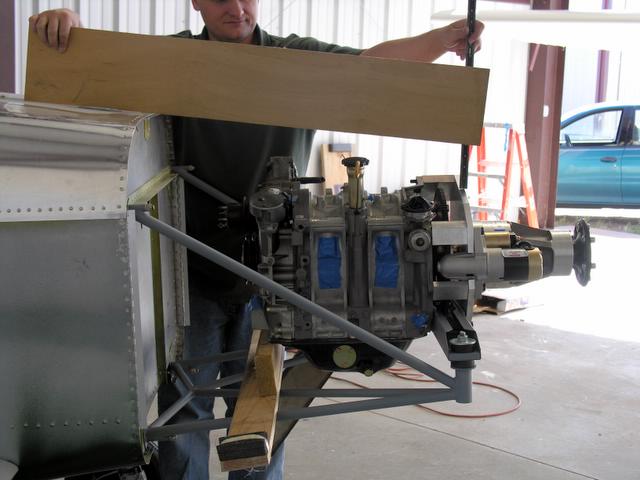
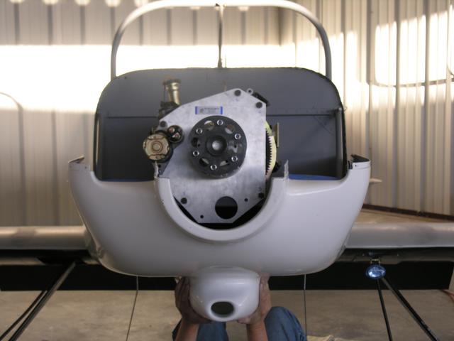
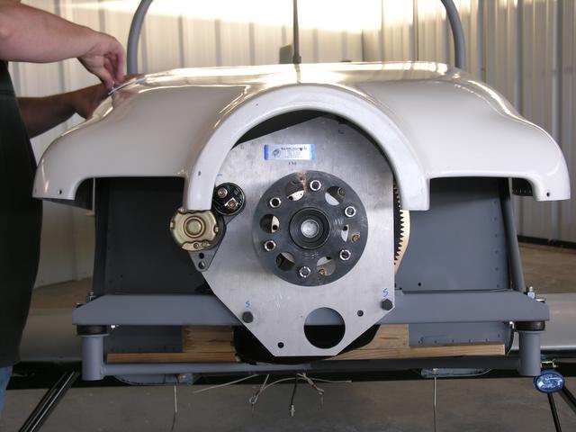
In the first photo, we see the mounted 13b from the front. You can the
the 1-degree tilt to the right issue we'd mentioned a few weeks back.
You can also see (if you look real close) the flex of the SBeam from the
engine load. I wonder whether the tilt to the right is the source of
the interference for the VAM.
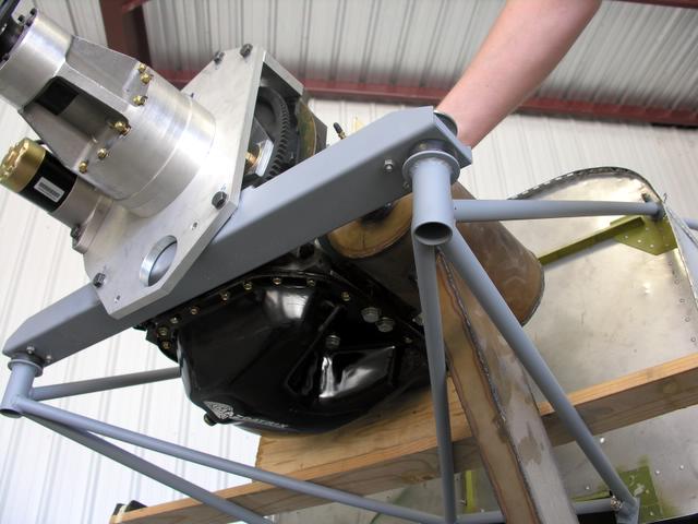
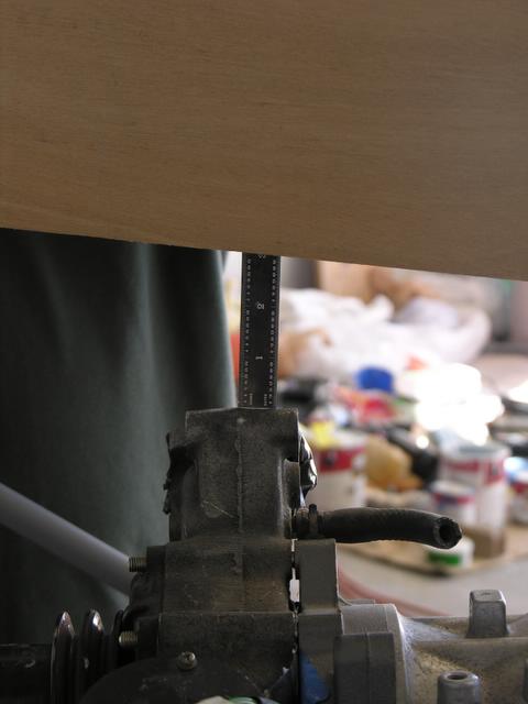
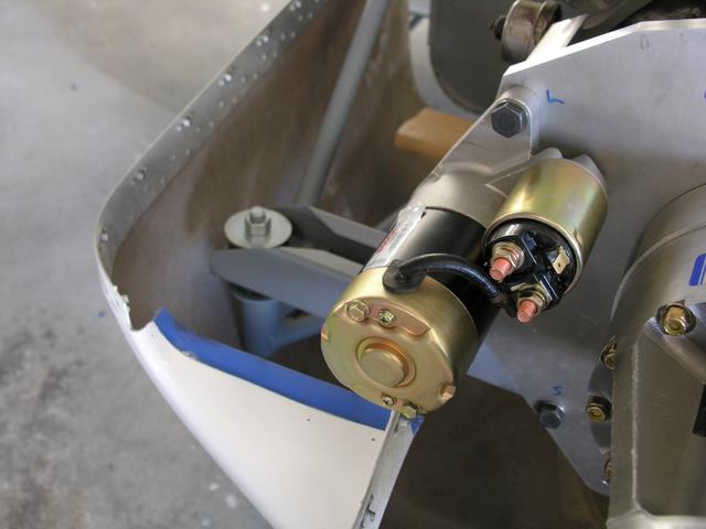
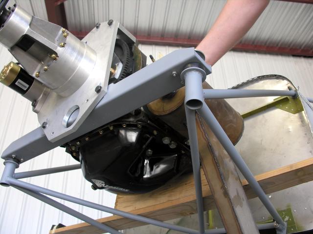
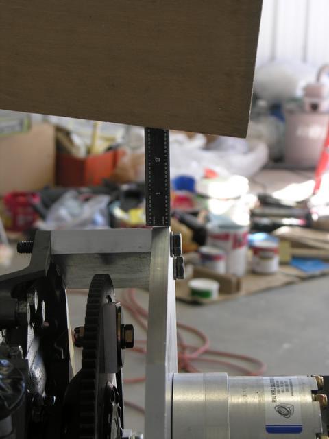
Photo 2 shows the interference. Cutting the exhaust tube & increasing
aft tilt will allow it to clear the tube.
Photo 3 was supposed to show the flange not seating - but you can't see it.
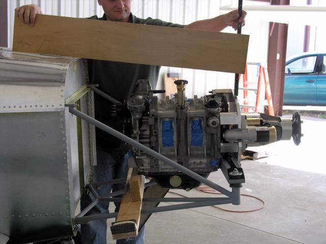
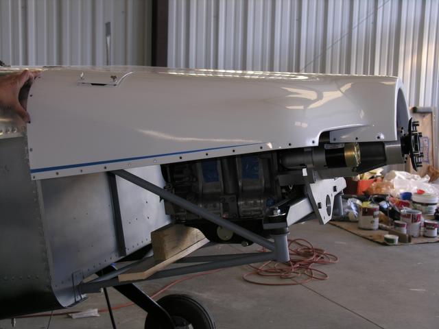
Photo 4 shows the vertical clearance under a cowl for the whole setup.
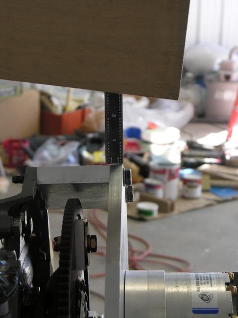
Photo 5 shows 3 inches of clearance at the top of the redrive mount plate.
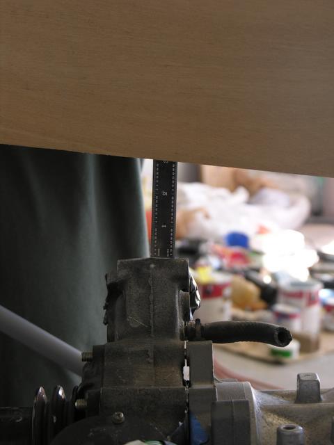
Photo 6 shows 3 inches of clearance at the top of the water pump.
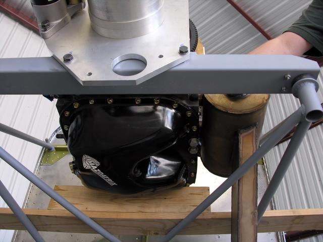
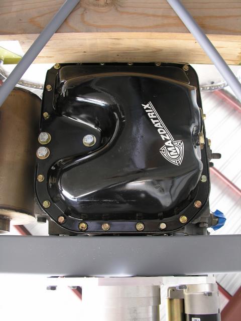
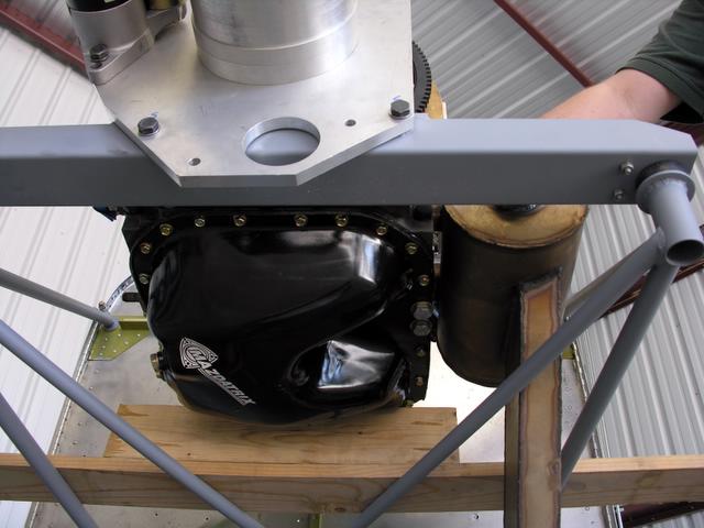
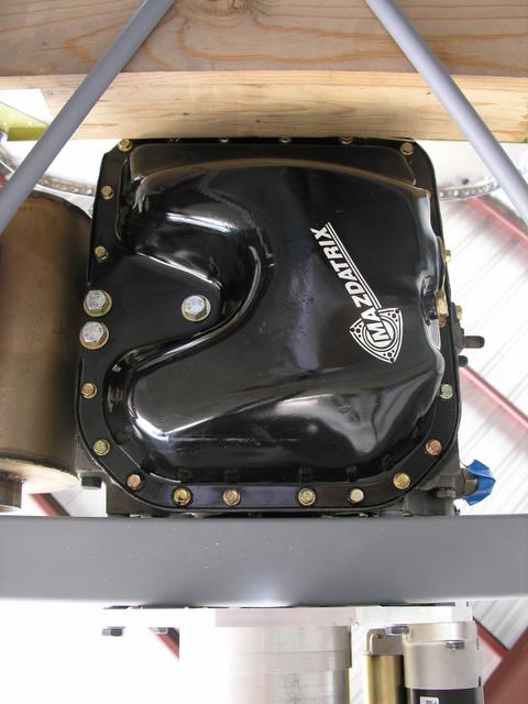
Photo 7 shows the oil pan, since there was some debate on whether we had
a std or large capacity one.
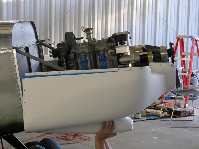
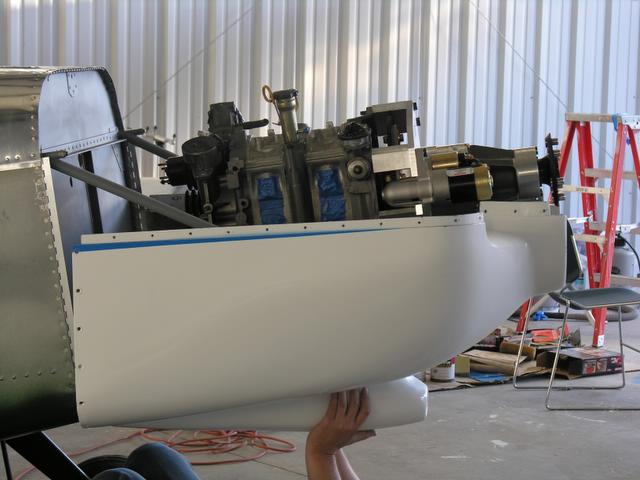
Photo 8 shows a relatively stock M2 bottom cowling. Interference by the
vertical mount tubes prevent a perfect fit. Not big deal, our bottom
will have to be blockier up front anyway for the shark mouth scoop.
Photo 9 shows things up front looking good.
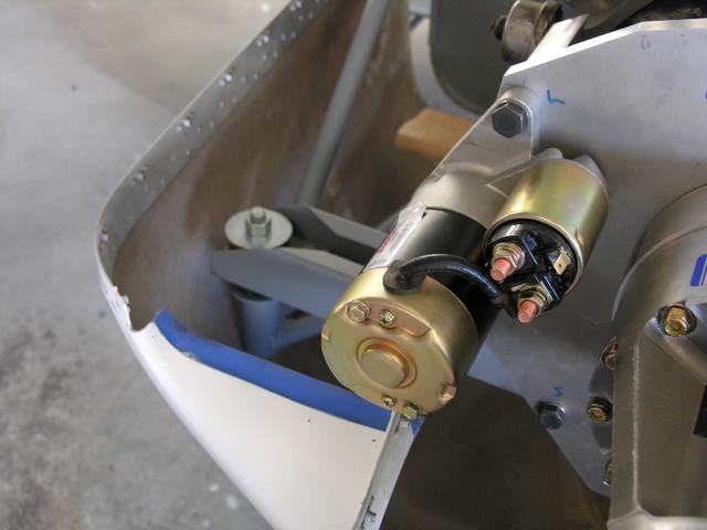
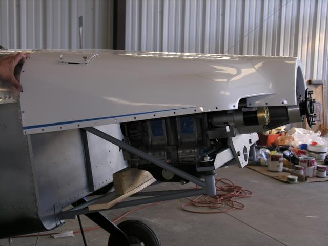
Photo 10 shows an inteference by the starter motor. Again no big deal,
since we can massage our cheeks to not do this.
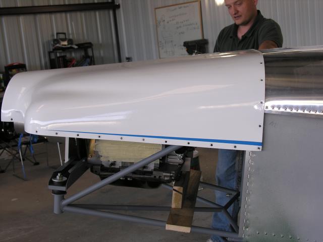
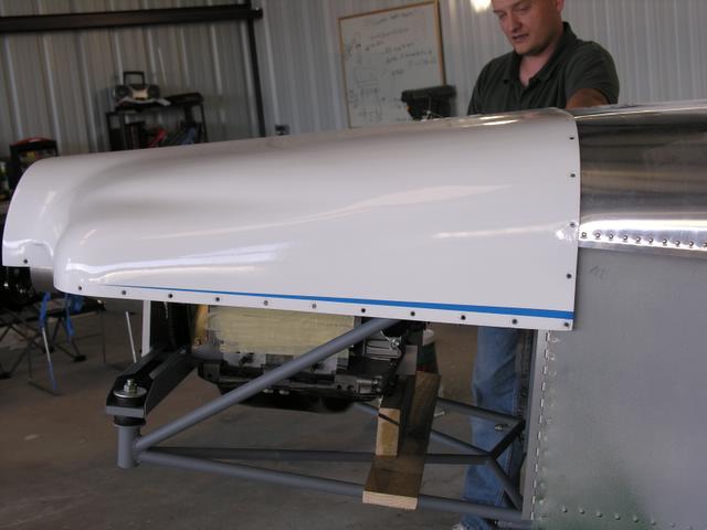
Photo 11 shows the top fitting nicely. We have it pulled back because
our length upfront is about 3/4" less than this cowl was made for.
(That's me holding it on btw).
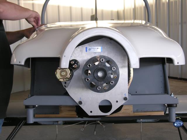
Photo 12 shows the fit working pretty well up front. Same inteference
by the starter motor.
Photo 13 shows trying to get as close as possible to actual fit. You
can see the roughly 3/4 pullback at the rear. Up front the distance
from prop flange to cowling is about right to accomodate the spinner.
Mark
The Rotary Engine NewsLetter. Powered by Linux.
ACRE NL web site.
http://www.rotaryeng.net
Copyright 1998-2005 All world wide rights reserved.