Hello Paul-
Some shots of the install for the slide throttle & the intake.
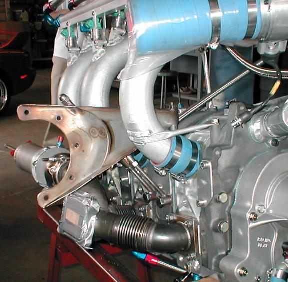
Photo 1 shows the slide throttle mounted on the intakes. Everything
lined up as expected & went on hey-diddle-diddle. We disassembled the
slide throttle first and spent spent some time deburring the edges &
dressing the aluminum where the Teflon slides. One note - the slide
does not achieve a full-off position -- it has a slight opening at the
full closed position. We suspect this was intentional.
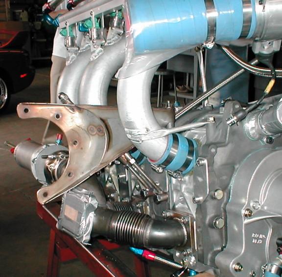
Photo 2 shows an interference on the slide throttle. In this case, we
see the bolt holes for the throttle body interfere with the mounting
flanges for the intakes. We will need to cut the mounting flanges at
45-degrees to open up access to the back of the throttle body for
bolts. No, we can't simply drill through -- the hole would be at the
very edge for some of the hole. 4 Interferences per intake flange. You
might want to tweak the design to move the holes off the flanges.
Photo 3 and 4 show the approximate position of the injectors vs. the top
of the cowling. Note that this appears to be an interference. One
question that had us wondering was exactly how the manifold was to be
attached to the slide throttle. Not sure if the intent was to weld it
on, or to flange the manifold & bolt it per the other side of the
throttle body. Regardless, our plan it get some 'altitude' by having
the manifold enter the throttle body at an ever so slight angle. This
will have the effect of rotating the injectors down a bit -- we're
shooting for 3/4 " below the estimated cowl height. This will have the
intakes pointing down toward the engine a bit, but nothing we can't work
with.
Need some guidance on where/how to mount the fuel pumps. I'm thinking
vertically on the firewall. Plumbed in parallel or serially?
On another note, finally got a ride in a M2 this morning. My
conclusion: we have wayyyy more power in the 13b than we really need.
Two heavy guys, one hot morning, one IO-230 = 1500fpm climb. Our
tentative plan is to program one of the EFIs for raw power & the other
for fuel-sipping economy. Should be fun to experiment...
Closer & closer...
Mark & Mark
Did we luck out or what? :)
Yes on the slight opening. Don't want to pull the throttle and
have the engine quit. Can be adjusted by trimming the Teflon.
Yes I knew you were going to have to trim the flanges. Yours is
a hybrid. Old and new design. The new Rev 11 design we have the flanges
sharing the bolts. There are only six bolts holes in the new larger
flanges and they line up with the holes in the slide throttle plate.
Simplified.
Tig weld the tubes on to the outer slide throttle plate. Skip around
and do it slowly so the plate does not warp too much. There is an
option but it will take new fuel rails or perhaps you can cut the
existing fuel rail in half and use it. The option is rotate both tubes
back about 20 degrees. That will give a bit more cowl clearance.
A cleaner way is to make new tubes with new injector holders.
Probably not worth the effort as a little bump on the top of the
cowl will take care of the clearance problem with the current
fuel rail and tube angles.
I would not do that last tube rotating trick. Might affect the tuning.
We went to great lengths to make the runners as smooth as possible
at WOT which is were you will run 90% of the time.
A little bump in the cowl won't hurt.
Mount the high pressure fuel pumps as low as you can get them and as
close to the fuel tanks as you can get them. This is very very important
as they will cavitate at the blink of an eye. Plumb them in parallel.
they are supposed to have a one way valve that prevents back flow.
Fuel selector valves should be double layer to send the return fuel
back to the tank you are drawing it from. Very very important. They should
also have a well defined detent. Vent the tanks up high but don't
point the vents forward into the air stream. One plugged vent can empty
the non plugged vented tank in a matter of minutes at 140 MPH and above.
Follow the Mustang II plans for fuel plumbing as close as possible given
the return line problem. What ever you do check with us. Fuel plumbing
mistakes can be deadly.
Looking good Mark you will have one fast airplane down low and up
high for a normally aspirated engine.
Take it easy when you take off the first time.
Can't wait to see this thing fly.
Paul Lamar
Good evening Paul from SA,
these guy's really doing an awsome job of work. Could'nt help noticing the
blocked off stock intakes and your new intake straight out the rotar
housings i presume. Are there significant gains in extra horsepower and
approx. how many more at what rpm.
I presume your abbreviation WOT stands for no turbo.
thanking you Craig
WOT Is wide open throttle.
Under ideal circumstances is 100 HP at 9000 RPM.
http://www.rotaryeng.net/300-HP-p-port-1980s.jpg
We are shooting for 250 HP at 7500 RPM.
A regular 2nd gen side port engine is about 200 HP at 7500 RPM.
Mild street porting. That includes the low power four port RX8 engine.
The six port RX8 engine should be about 10 HP more at 7500 RPM.
Paul Lamar
Paul,
Is there any difference in performance from having the throttle so close to
the block compared with say in front of the intercooler like on you
intercooler/manifold design? In the later case you only have to throttle
one pipe then.
Doug in Japan
True but it would most probably idle better if it was close to the block.
Althouh people have built turbo p-port engines with one throttle.
Here is an example. I am not sure how it idled.
Paul Lamar
The Rotary Engine NewsLetter. Powered by Linux.
ACRE NL web site.
http://www.rotaryeng.net
Copyright 1998-2005 All world wide rights reserved.