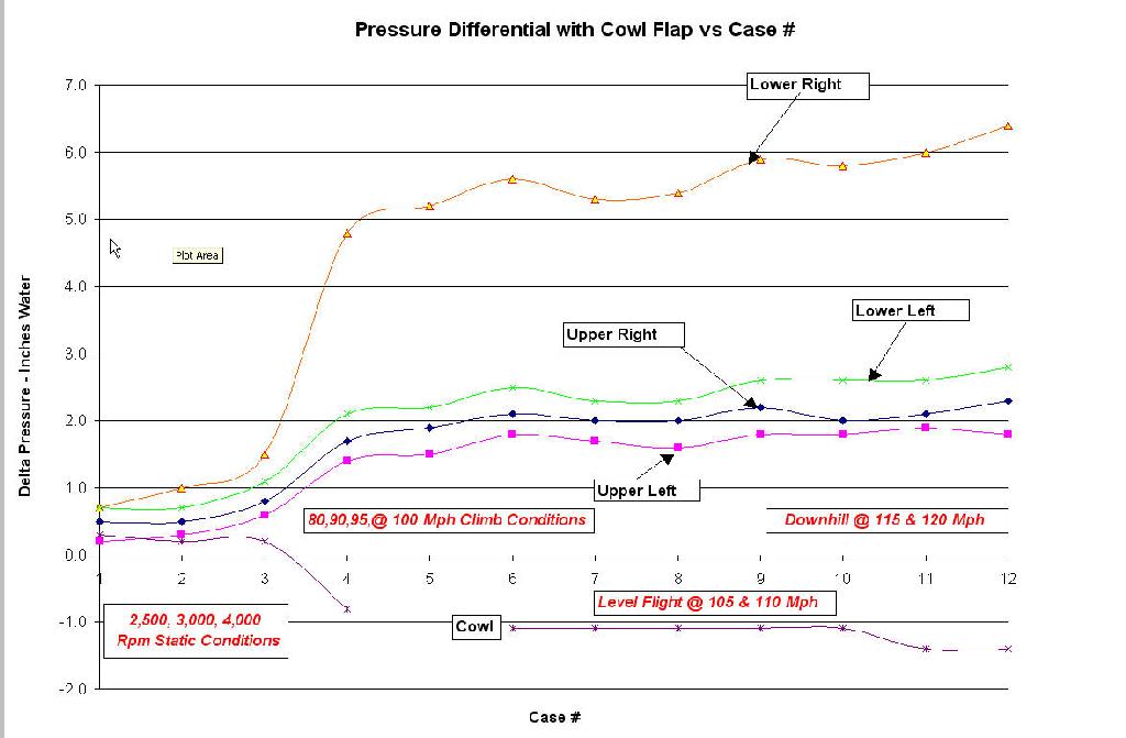
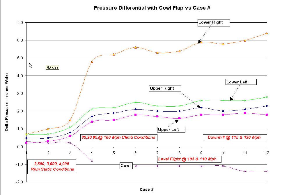
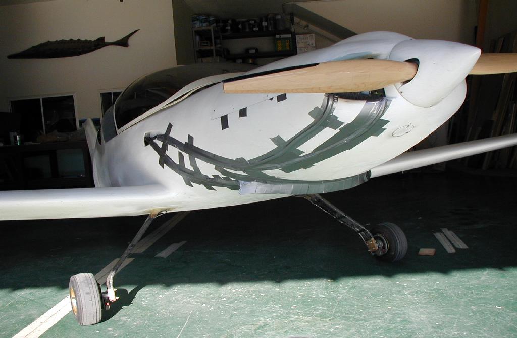
We doubled the pressure differential and hence the flow through
the rad by adding this cowl flap. The data report will
be along shortly. Coolant temp dropped 20 to 30 degrees
but it was a cooler day. For that reason the jury is still
out on whether the cooling is adequate yet.
The problem here is it is tough to install
adjustable cowl flaps as the bottom of the Pulsar cowl
opening is a compound curve. That means we need segmented
flapettes :) And a complicated control system in the bargain.
-----------------------------------------------------
Here is the first idea in the first two 3Ds.
Lots of little bits a pieces.
Watch like :) Yuck too much fabrication work.
The third 3D is the easy way. You cut a rectangle out
of the bottom of the compound curved cowl, add side plates and it
becomes the flap. The hinges are trick but easy if you know how
to design them. More on the hinges later. The gap is sealed
with silicone rubber.
------------------------------------------
OK here we go. This is a 3 inch wide 1/8th inch thick piece
of silicone rubber cowl sealing material from AirCraft Spruce
or McMaster Carr. Good to 500 degrees F. McMaster Carr also has
glass fiber reinforced stuff but it is a little too stiff for this
applications. The gap has got to be sealed anyway. This does double
duty.
Pop rivet it in with large washers on the rubber side or bolt
it in with flat head screws and large washers on the rubber side.
Do this with the flap set about half open.
If you are worred about it coming off a short section of piano
hinge in the center would be back up.
Nothing could be quicker or easier.
Paul Lamar
I'm usually pretty good at these things, but I am having a tough time
visualizing what's going on here based on these renderings. Maybe a zoom
out would help? Or different colors, or something.
Regards,
Matt-
Sorry.
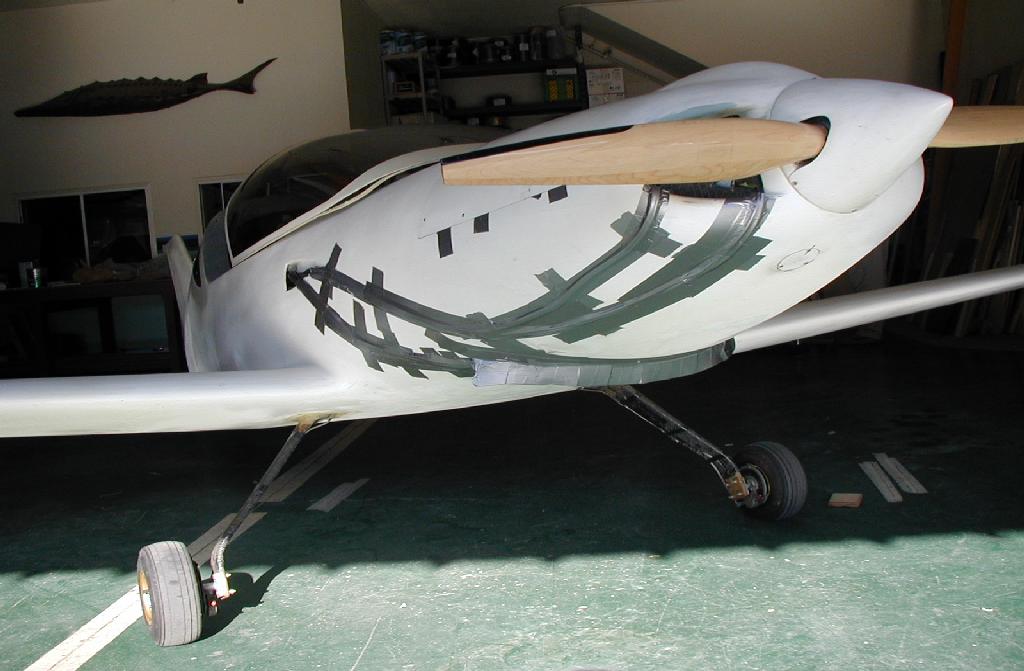
The the cowl is transparent in the last 3D so you are looking
in and down and back at the muffler standing outside the cowl on the
left front side. Here are a few pix to get you oriented.
The last 3D is zoomed out. No engine included. Only the huge
muffler required is shown.
Paul Lamar
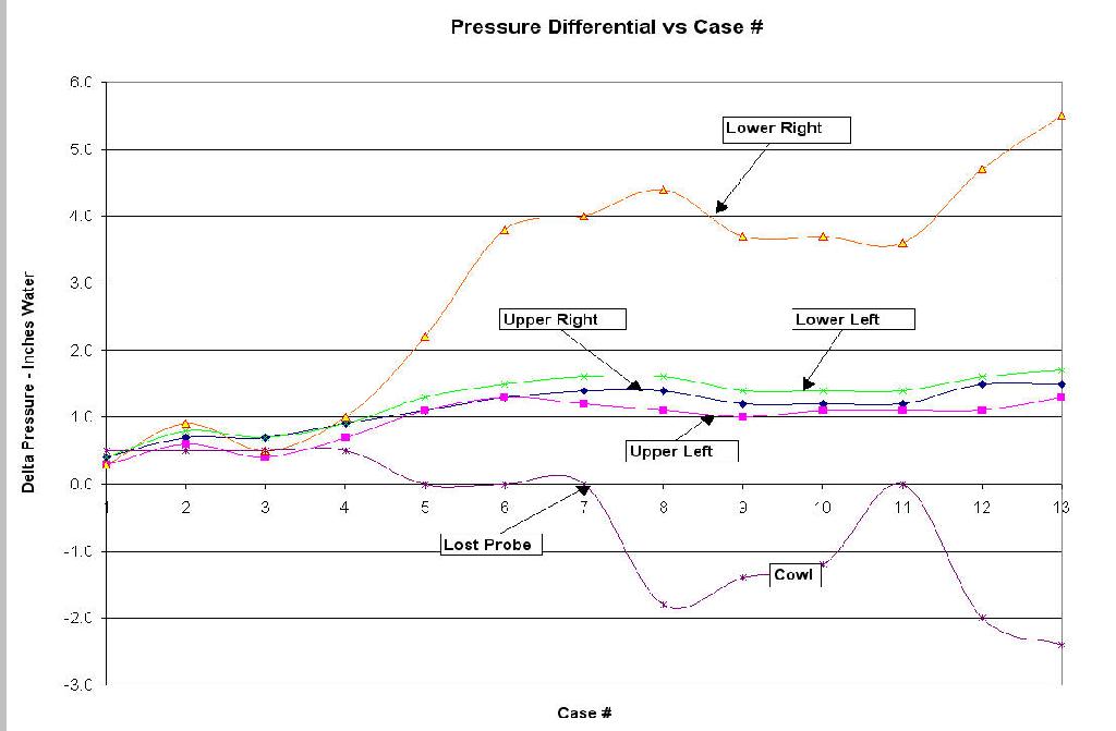
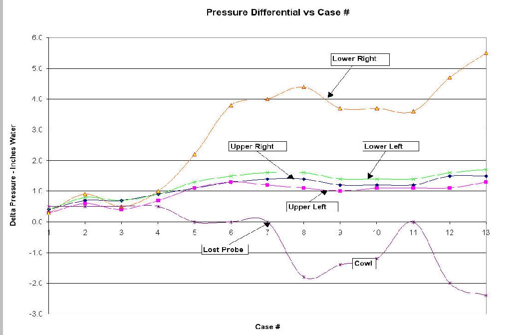
Here are some graphs of the results. This is the first time we
have quantified the affects of cowl flaps. A significant historical
event in the annals of liquid cooling. We owe a huge
debt of gratitude to Alex Kozlof for his excellent documentation
of the data and the use of his airplane and his test flying. Thank
you Alex. It is truly amazing that this inch and a half cowl
flap doubled the theoretical airflow through the heat exchanger.
I am looking forward to the day when Alex gets the movable
cowl flap in there. It will be well constructed like the rest of his
fine Pulsar. Alex happens to be an expert on carbon fiber, carbon
fiber composite fabrication as well as a distributor of carbon fiber.
Paul Lamar
--
The Rotary Engine NewsLetter. Powered by Linux.
ACRE NL web site.
http://www.rotaryeng.net
Copyright 1998-2005 All world wide rights reserved.