It appears, from the photo with the upper cowl removed, that the
radiator is angled backward with respect to the face of the cowl cheek
opening. The angle appears to make the right side face of the radiator
substantially further from the cowl cheek opening face than the left
side face of the radiator. That difference will allow more external
diffusion to occur, and could account for the pressure differences
between the right side (4-7 & 2-5) and left side (1-8 & 3-6).
The angle also appears to make the top of the radiator face somewhat
further from the cowl cheek opening face than the bottom of the radiator
(but not as pronounced as the left-right difference). But since the
lower positions (2-5 & 3-6) have more pressure differential than the
upper positions (4-7 & 1-8), I'm perplexed. The prop appears to sweep
bottom-to-top on the right side of the cowl (where the radiator
measurements were taken), therefore I would expect the relative airflow
to favor the upper positions over the lower positions, causing the
pressure differences on the upper positions to be greater than the lower
positions. Are we certain of the manometer setup?
Also, can we get a few more photos of the radiator position with respect
to the cowl? A directly overhead shot (relative to the
*flying*
attitude, not parked attitude) of the radiator in the lower cowl with
the upper cowl removed might be helpful.
The under-cowl negative pressure (relative to static)
*seems* useful for
encouraging airflow through the radiator, but the under-cowl pressure
relative to the cowl exit pressure is the
*real* measurement to take.
We want the under cowl pressure to be lower than cowl cheek face, but
higher than the cowl exit area pressure. If the cowl exit area pressure
is too high, then adding a cowl flap there won't help (to which Vance
was referring).
Russell Kent
There is no doubt the rad is a bad position. Unfortunately too many people
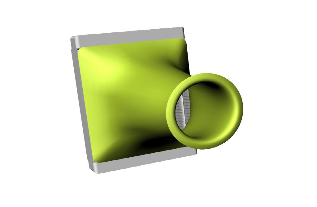
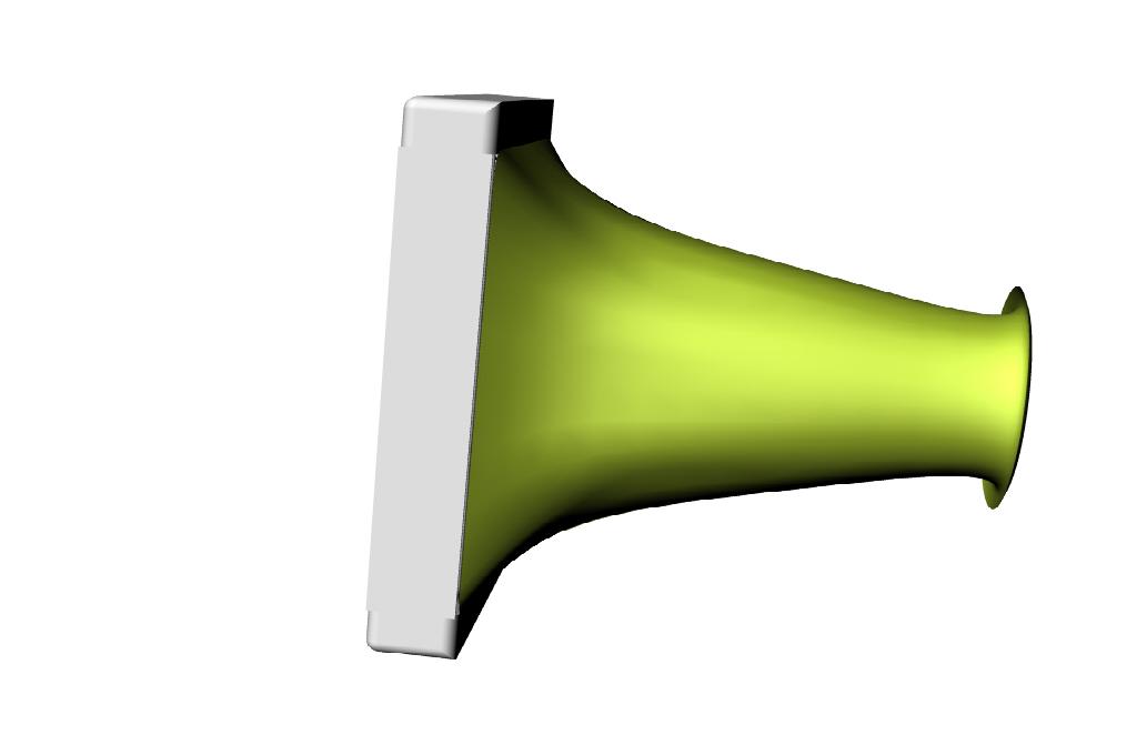
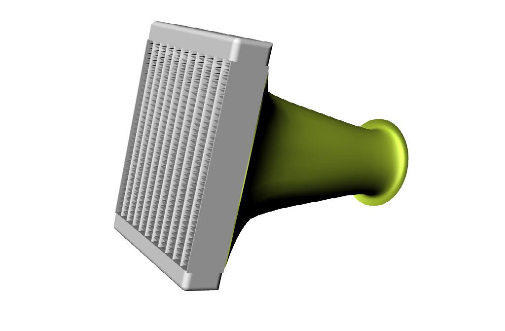
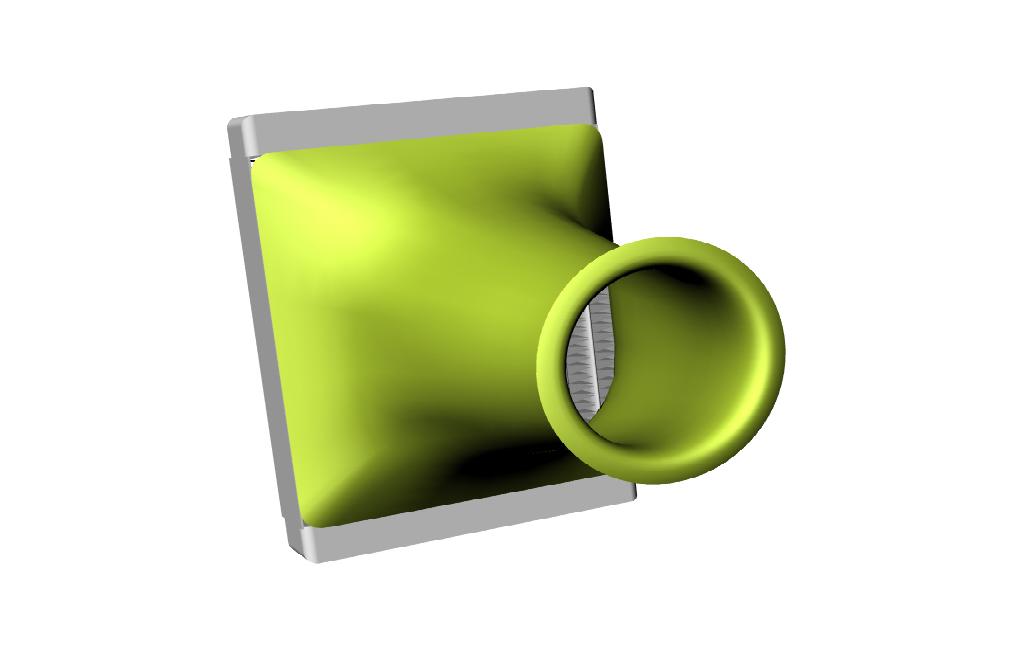
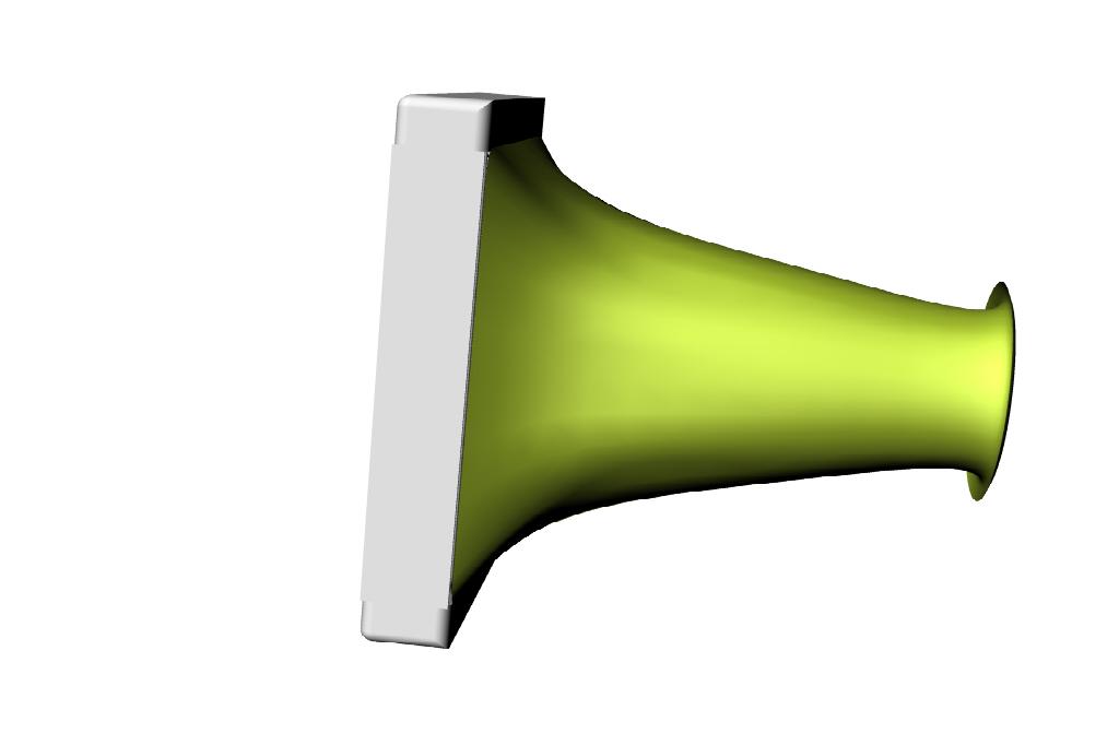
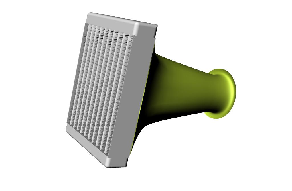
make this mistake. The perfect K&M diffuser would look something like
this. The Pulsar core is 9 by 8 inches making the length of the diffuser
about 10 inches or 11 inches. There just is never enough room under
the cowl for this type perfect diffuser.
If you tilt or off set the core relative to the perpendicular
axis all bets are off on uniform air flow distribution through the core.
This Pulsar core is both offset and tilted not to mention way
too close to the scoop.
In order to achieve perfectly uniform flow through the core either
CFD must be used or extensive experimentation with many different diffuser
shapes along with 2D extensive pressure instrumentation of the walls
of the experimental diffuser. IMHO I don't know anyone on here including
myself that is up for that :)
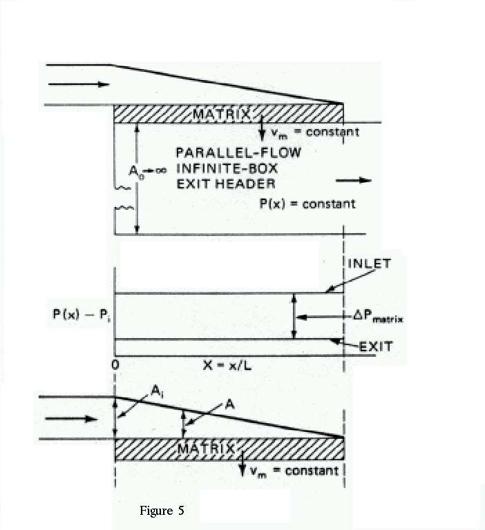
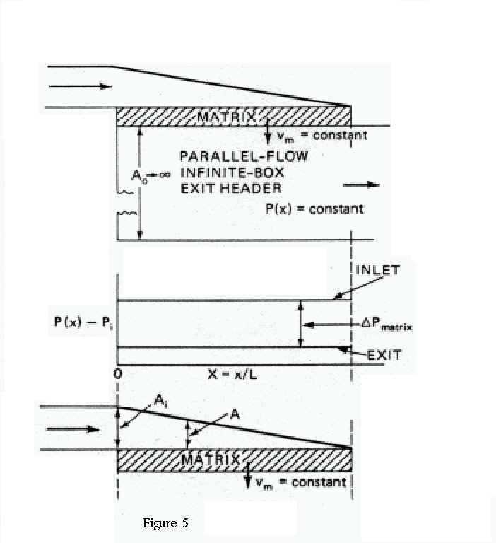
Again I say the Kays and London wedge shaped diffuser is better for
our applications.
Paul Lamar
The Rotary Engine NewsLetter. Powered by Linux.
ACRE NL web site.
http://www.rotaryeng.net
Copyright 1998-2005 All world wide rights reserved.