Russell Kent wrote:
The angle also appears to make the top of the radiator face somewhat
further from the cowl cheek opening face than the bottom of the
radiator (but not as pronounced as the left-right difference).
But since the lower positions (2-5 & 3-6) have more pressure
differential than the upper positions (4-7 & 1-8), I'm perplexed.
The prop appears to sweep bottom-to-top on the right side of the
cowl (where the radiator measurements were taken), therefore I
would expect the relative airflow to favor the upper positions
over the lower positions, causing the pressure differences on
the upper positions to be greater than the lower positions.
Are we certain of the manometer setup?
Alex,
Thanks for the additional overhead photo, along with the side shot and
the backside shot.
I think the pressure data indicates that you have an air leak at the
top, at the radiator & upper-cowl seal. Check this area carefully, as
air leaks can defeat even the best designed duct systems.
Also, you need a larger heat shield around those exhaust pipes. I see
that you have one on the close exhaust pipe, but it needs to be larger
(in area) and the further exhaust pipe also needs a heat shield.
I doubt that it's possible to make this change at this point... But if
the radiator were turned such that the face was closer to parallel to
the side of the aircraft, then a wedge diffuser (Kays & London) should
be possible, with the airflow drawn from the outside of the cowl cheek
opening, passing through the radiator towards the engine. The backside
photo shows what appears to be a cowl rib that would be problematic,
however.
Russell Kent
I think you are right Russell. Here is a good picture of the leak.
We have decided to build a new, better sealed, stand alone diffuser.
More on that later.
Paul Lamar
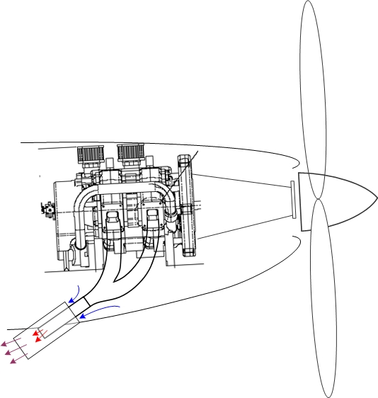
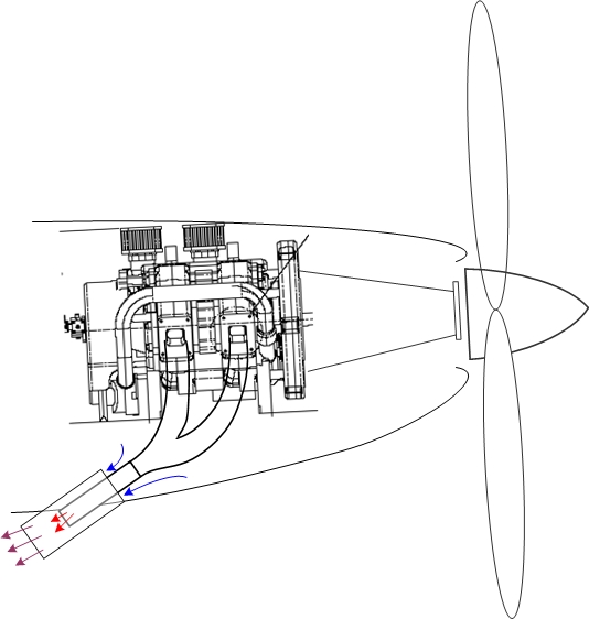
AUGMENTOR TUBE: It seems something I've flown a long time ago had a
lightweight SS tube around the exhaust pipe where it protruded from the
bottom of the cowling. The tube forms an annulus through which the
relatively high velocity exhaust gasses are expelled. The exhaust pipe is
substantially short of the end of the augmentor tube. The exiting exhaust
gases drag air out of the cowling, thus augmenting airflow through that
volume. The cowling should fit fairly well around the augmentor tube. It
could also serve to prevent heat radiation into the engine enclosure. Rough
sketch attached.
Do any of you guys employ this technique to enhance airflow through the
cowling? What are the pros and cons as you see them?
Jim Beckman
Austin
Yep. We covered that stuff in
http://www.rotaryeng.net/cooling.html
Nice drawing Jim. Thanks.
Paul Lamar
The Rotary Engine NewsLetter. Powered by Linux.
ACRE NL web site.
http://www.rotaryeng.net
Copyright 1998-2005 All world wide rights reserved.