Paul, I measured the longerons on the Legacy. They come out to
9.25" below
the top of the cowl or 1.125" below the top hardpoints. The
drawing shows
the thrust line to be 1.5" below the longeron line, then angles down 1
degree and to the right 2 degrees.
Bill Bradburry
Paul, I was incorrect when I indicated above that the drawing shows
the
thrust line to be 1.5" below the longeron line. Another look at the
drawing shows it to be 2.5" instead.
Bill Bradburry
Can you take a direct side shot of the existing motor mount?
Also Jerry could measure the current existing mount when he gets it
and determine the thrust line from those measurements since
he has dwg's on Lycoming dynafocal mounts.
Paul Lamar ...No rotor no motor.
I only have the pics that I sent. The mount is not here now so I
can not
take more pics. I will send the mount to Jerry when we are ready
to start
the modification.
Bill Bradburry
OK No problem Bill. Jerry can used these dwg to figure out
exactly where the thrust line is from the old mount
---------------------------------------------------------------
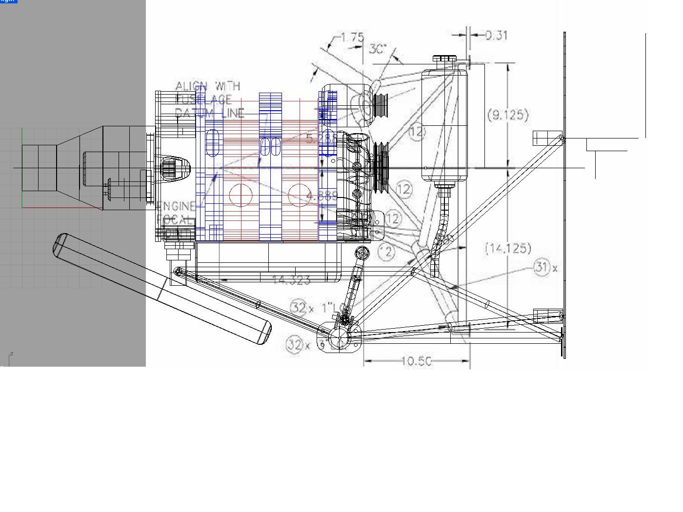
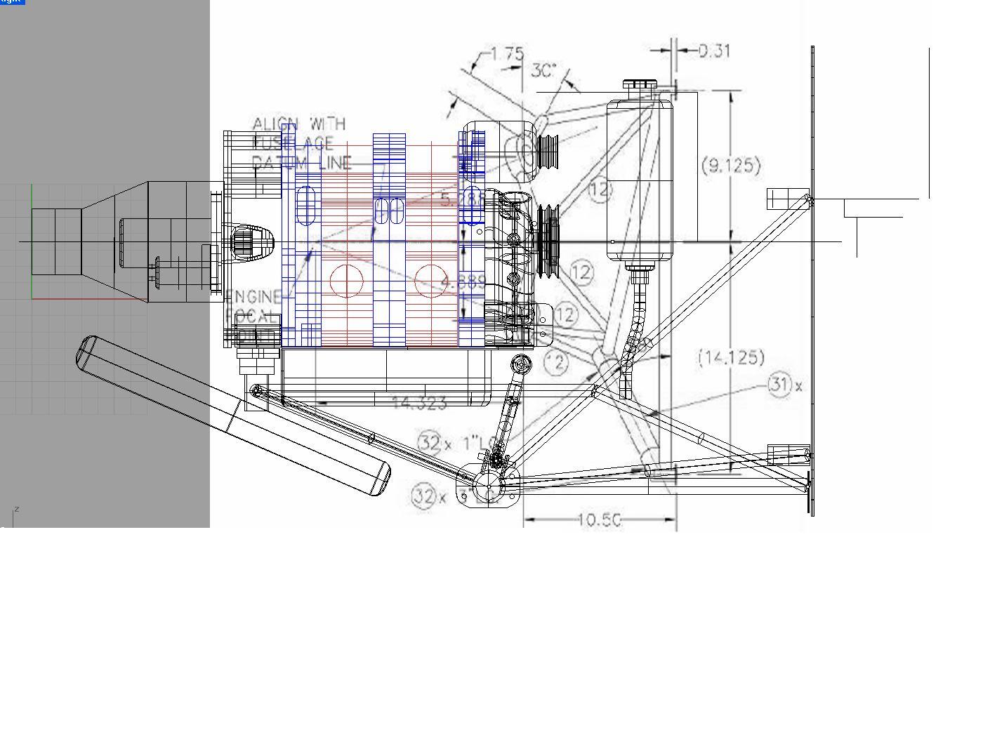
From this overlay the engine looks higher and not lower.
Not to worry Bill we will figure it out exactly when we get the
old mount.
Paul Lamar ...No rotor no motor.
Paul and Bill, I am not worried about determining the thrust line
once I have the MM. I am concerned that the strut may be affected by
the height of the engine in some way we did not anticipate. Using
Rhino and the proper thrust line NOW at this phase of the design is
extremely important in my view so that we know how it will turn out
before starting.
Jerry
I can't get it any closer than this without knowing the exact position.
When are you getting the motor mount? If we must fit it in the cowl
we should also have the cowl.
Paul Lamar
Paul, Take the picture of the Legacy in this overlay, and combine the thrust
line you now have, with the thrust line shown in the drawing that Jerry has
showing the thrust line of the Dynafocal mount. I expect that the thrust
lines will line up exactly. (at least within the error of my measurement
:>) )
Try it, you will like it!
Bill
Good idea. I'll try the dynofocal drawings in a bit.
The problem with the last overlay front view pic is it was taken looking
down on the mount. Also the camera was a bit too close to the mount
so you get distortion from that source as well. It works best when
you are far away from the object you are trying to measure.
The side view was much better because it used this jpg where
the camera was well away from the motor mount..
This is a very powerful technique that I discovered just recently
built into Rhino.
I also used the drawing as a back ground to Check on the dimensions
of the firwall hard pounts.
Paul Lamar ...No rotor no motor.
Is this what you had in mind Bill?
Paul Lamar ...No rotor no motor.
The Rotary Engine NewsLetter. Powered by Linux.
ACRE NL web site.
http://www.rotaryeng.net
Copyright 1998-2005 All world wide rights reserved.