Hello Paul,
I took the compressor housing off today and but I am unable to get the
traction drive housings to separate. It looks like they used some red
Locktite on the halves. The fit is superb with no way to get a knive edge
between them. I don't want to muck it up before we get a chance to test it.
More importantly is to get the compressor wheel retaining nut off. It is a
reverse thread and has a special kind of nut which doesn't fit normal
socket wrenches. It looks like a torrus screw in relief.
BTW ROTREX updated their website and the installation manual has a good
exploded view of the unit. There are is a sealed bearing on the pulley side
and from the illustration it appears to be another one a short distance
inboard. This would make sense as the side loads for transmitting 60KW would
be substantial.
In the factory they showed me a few parts. One was the die cast holder for
the three planetary rollers that connects to the pulley input shaft.
Say what is your take on Racing Beat's aluminum side housings? With a P-port
in mind, they would be an good option if durable enough for my engine. Those
with Renesis rotors and front housing would make a superb aircraft power
plant.
Doug
Take some pictures of what ever you have. Any and all pictures will help.
History is not good on the RB aluminum side housings. People have had problems
with the coatings. Jim may have changed the coatings by now but I can't nail him
down on what he is actually using currently. IMHO if it is not silicon nitride
detonation gun coatings forget it.
Paul Lamar
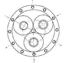
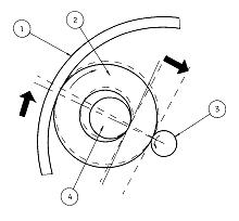
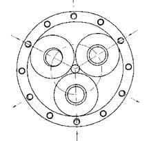
The new web site is very very interesting. They have changed their logo so
it is much much more difficult if not impossible to figure what they
are doing :) Well we will just have to find the patent if it is
really granted. Looks like they are going with trade secrets :)
Fortunately I figured out the principle looking at the old logo :)
http://www.rotrex.eu.com/
Paul Lamar ...No rotor no motor.
This one is interesting.
-------------------------------------------------------
United States Patent 6,796,126
Hasegawa , et al. September 28, 2004
Supercharger
Abstract
A speed increasing gear used in a supercharger has a center roller connected to an
output shaft, an outer wheel arranged eccentric to the center roller, and a plurality
of intermediate rollers arranged within an annular space in which a width of the
center roller with respect to a diametrical direction is uneven with respect to a
circumferential direction of the center roller. The annular space is provided between
the center roller and the outer wheel, and a pivot of at least one intermediate
roller is movably arranged in a circumferential direction and a radial direction of
the center roller.
Inventors: Hasegawa; Hiroyuki (Shizuoka, JP); Yoshimoto; Shinya (Shizuoka, JP);
Itoh; Hiroyuki (Kanagawa, JP); Dairokuno; Satoshi (Kanagawa, JP)
Assignee: HKS Co. Ltd. (Fujinomiya, JP); NSK Ltd. (Tokyo, JP)
Appl. No.: 320131
Filed: December 16, 2002
Foreign Application Priority Data
Dec 27, 2001[JP] 2001-398353
Current U.S. Class: 60/605.1; 123/559.1; 123/561
Intern'l Class: F02B 033/44
Field of Search: 60/605.1 123/559.1,559.2,559.3,561
References Cited [Referenced By]
U.S. Patent Documents
2344078 Mar., 1944 Brissonnet et al.
4249750 Feb., 1981 Kantner 280/216.
4649307 Mar., 1987 Bech 310/99.
5133325 Jul., 1992 Winkelmann 123/559.
5443054 Aug., 1995 Tateno et al. 123/559.
6039668 Mar., 2000 Kolstrup.
6231302 May., 2001 Bonardi 415/105.
6397808 Jun., 2002 Tanaka et al.
Foreign Patent Documents
04-203421 Jul., 1992 JP.
10-316081 Dec., 1998 JP.
11-502596 Mar., 1999 JP.
11-294548 Oct., 1999 JP.
2001-59459 Mar., 2001 JP.
2001-271897 Oct., 2001 JP.
2002-221263 Aug., 2002 JP.
WO 96/30670 Oct., 1996 WO.
WO 02/064997 Aug., 2002 WO.
This sure sounds like it.
------------------------------------
BACKGROUND OF THE INVENTION
1. Field of the Invention
The present invention relates to a supercharger for vehicle engines.
2. Description of the Related Art
Conventionally, there is a supercharger in which a rotation speed of an input shaft
is increased by a speed increasing gear so as to be transmitted to an output shaft,
and an impeller is provided in the output shaft.
In order to obtain a high speed increasing ratio, Japanese Patent Application
Laid-Open No. 4-203421 proposes a structure using a planetary gear mechanism and
Japanese Patent Publication No. 11-502596 proposes a structure using a planetary
friction roller mechanism, as the speed increasing gear.
In the structure using the planetary gear mechanism described in Japanese Patent
Application Laid-Open No. 4-203421, there are problems of gear noise generated by
high speed rotation and a reduction in service life of a bearing due to vibration. In
order to reduce the problems relating to the noise and the vibration, it is necessary
to improve the working accuracy and the assembling accuracy of the gears, resulting
in decreased productivity.
In the structure using the planetary friction roller mechanism described in Japanese
Patent Publication of No. 11-502596, there are the following problems a to c in view
of the structure thereof for fastening a friction roller such as a planetary wheel
and a sun shaft by a flexible outer ring.
a. When the rotation becomes high (i.e., at an impeller rotation speed equal to or
greater than 75000 rpm), a slip of the friction roller is generated, and it is
impossible to transmit a driving force for supercharging to the impeller.
b. In order to prevent slippage at high speed rotation, it is necessary to increase a
force by which the outer ring fastens the friction roller. Accordingly, an undesired
fastening force is always applied to the friction roller at low speed rotation, and a
driving loss at the low speed rotation is great.
c. In order to prevent slippage at high speed rotation and secure a suitable
fastening force at low speed rotation, it is necessary to employ an exclusive
assembling step of applying a high working accuracy, a selectable fitting, a suitable
shrinkage fitting of the outer ring or the like to the outer ring and the friction
roller. As a result, the productivity is deteriorated.
SUMMARY OF THE INVENTION
An object of the present invention is to produce a supercharger which does not
generate a slip at high speed rotation and a driving loss at low speed rotation,
which has low noise and low vibration, which has a light weight and a compact size,
and which can be produced at a high productivity.
Another object of the present invention is to improve lubricating and cooling
performances of a bearing portion in an output shaft, so as to make it possible to
adjust a thrust load and improve durability.
According to the present invention, there is provided a supercharger in which a
rotation speed of an input shaft is increased by a speed increasing gear so as to be
transmitted to an output shaft, and wherein an impeller is provided in the output shaft.
The speed increasing gear comprises a center roller connected to the output shaft; an
outer wheel arranged eccentric to the center roller; and a plurality of intermediate
rollers arranged within an annular space in which a width of the center roller with
respect to a diametrical direction is uneven with respect to a circumferential
direction of the center roller. The annular space is provided between a driven side
cylindrical surface corresponding to an outer circumferential surface of the center
roller and a drive side cylindrical surface corresponding to an inner circumferential
surface of the outer wheel. Respective outer circumferential surfaces of the
intermediate rollers are formed as power transmitting cylindrical surfaces.
A pivot of at least one intermediate roller is movably arranged in a circumferential
direction and a radial direction of the center roller.
BRIEF DESCRIPTION OF THE DRAWINGS
FIG. 1 is a cross sectional view which shows a supercharger according to a first
embodiment;
FIG. 2 is an end elevational view along a line II--II in FIG. 1;
FIG. 3 is an end elevational view which shows a modified embodiment of a speed
increasing machine;
FIG. 4 is a cross sectional view which shows an oil circulating path;
FIG. 5 is a cross sectional view which shows a supercharger according to a second
embodiment;
FIG. 6 is a cross sectional view along a line VI--VI in FIG. 5;
FIG. 7 is a cross sectional view which shows a bearing portion;
FIG. 8 is a cross sectional view which shows a supercharger according to a third
embodiment; and
FIG. 9 is an enlarged cross sectional view of a main portion which shows a
supercharger according to a fourth embodiment.
DESCRIPTION OF THE PREFERRED EMBODIMENTS
(First Embodiment)(FIG. 1 to FIG. 4)
An automotive supercharger 10 in FIG. 1 comprises an input shaft 11, a speed
increasing gear 30 that transmits increased rotation to an output shaft 12, a pulley
13 driven by an engine output and fixed to the input shaft 11, and an impeller 14
provided in the output shaft 12.
The supercharger 10 is structured such that a compressor housing 16 is fixed to a
center plate 15. The center plate 15 supports the output shaft 12 by a bearing 17.
Reference numeral 18 denotes an oil seal. The compressor housing 16 receives the
impeller 14, and is provided with a suction port 21, a supercharging passage 22 and a
scroll 23.
The speed increasing gear 30 is a friction roller type speed increasing gear
utilizing a wedge effect, and is provided with a speed increasing housing 31 in such
a manner as to be fixed to the center plate 15, and the speed increasing housing 31
supports the input shaft 11 by a bearing 32. Reference numeral 33 denotes an oil seal.
The speed increasing gear 30 is provided with a center roller 34 integrally and
concentrically arranged in an end portion of the output shaft 12, in an inner portion
of the speed increasing housing 31.
The speed increasing gear 30 is provided with an outer wheel 36 integrally and
concentrically arranged in an end portion of the input shaft 11 via a disc portion
35, in the inner portion of the speed increasing housing 31. An outer wheel 36 is
arranged eccentric to the center roller 34.
In the speed increasing gear 30, three intermediate rollers 38A to 38C are arranged
within an annular space 37 in which a width of the center roller 34 with respect to a
radial direction is uneven with respect to a circumferential direction of the center
roller 34 due to the eccentricity between the center roller 34 and the outer wheel
36. The annular space 37 is provided between a driven side cylindrical surface 34A
corresponding to an outer circumferential surface of the center roller 34 and a drive
side cylindrical surface 36A corresponding to an inner circumferential surface of the
outer wheel 36, in the inner portion of the speed increasing housing 31. The end
portions of three pivots 39A to 39C are respectively supported on the center plate 15
and a connection plate 41. The connection plate 41 is fixed to the center plate 15 by
connection bolts 41A (FIG. 4) and is received at a position in the inner portion of
the speed increasing housing 31 and along the disc portion 35. The intermediate
rollers 38A to 38C are rotatably supported by the pivots 39A to 39C, respectively.
The respective pivots 39A to 39C are arranged parallel to the center roller 34 and a
center axis of the outer wheel 36. In the respective intermediate rollers 38A to 38C,
outer circumferential surfaces thereof are formed as power transmitting cylindrical
surfaces 40A to 40C which roll in contact with the driven side cylindrical surface
34A of the center roller 34 and the drive side cylindrical surface 36A of the outer
wheel 36.
Two of the pivots 39B and 39C are fixed by pressing or inserting both end portions
thereof into supporting holes provided in the center plate 15 and the connection
plate 41 with no play. Accordingly, the pivots 39B and 39C do not displace in a
circumferential direction and a radial direction of the center roller 34 in the inner
portion of the speed increasing housing 31.
On the other hand, the pivot 39A is structured such that both end portions thereof
can freely displace in the circumferential direction and the radial direction of the
center roller 34 within the center plate 15 and a guide groove 42 provided in the
connection plate 41, and the intermediate roller 38A is formed as a movable roller.
The pivot 39A is pressed by a spring 44 corresponding to a pressing means which is
backed up by a spring receiver 43 provided in the center plate 15 or the connection
plate 41, and presses the movable roller 38A corresponding to the intermediate roller
to the center roller 34 and the outer wheel 36 in a direction in which a width of the
annular space 37 becomes narrow.
Accordingly, in the speed increasing gear 30, when the supercharger 10 is mounted to
the engine by using a mounting boss 24 provided in the center plate 15, and a driving
force is input to an input pulley 13 from the engine, the driving force is
transmitted to the outer wheel 36 from the input shaft 11. At this time, since the
outer wheel 36 and the center roller 34 are eccentric as mentioned above and the
annular space 37 mentioned above is uneven with respect to the circumferential
direction of the center roller 34, the movable roller 38A moves in a direction b in
which the movable roller 38A is exposed to the wedge effect between the outer wheel
36 and the center roller 34 according to a rotation of the outer wheel 36 in a
direction a, so that a pressing force c is generated among the driven side
cylindrical surface 34A of the center roller 34, the drive side cylindrical surface
36A of the outer wheel 36 and the power transmitting cylindrical surfaces 40A to 40C
of the intermediate rollers 38A to 38C. On the basis of the pressing force c, a
friction force is generated among the driven side cylindrical surface 34A of the
center roller 34, the drive side cylindrical surface 36A of the outer wheel 36 and
the power transmitting cylindrical surfaces 40A to 40C of the intermediate rollers
38A to 38C. The driving force transmitted to the outer wheel 36 is transmitted to the
center roller 34, and the center roller 34 rotates in a direction d. The rotation of
the center roller 34 generates a rotation of the integrally formed output shaft 12.
The impeller 14 fixed to the output shaft rotates, and air is sucked from the suction
port 21. This air is supercharged so as to be supplied to the engine from a chamber
pipe communicated with the scroll 23.
In this case, since three intermediate rollers 38A to 38C are substantially uniformly
arranged peripheral to the center roller 34, substantially the same pressing force as
the pressing force generated in the movable roller 38A corresponding to one of the
intermediate rollers is also generated in the guide rollers 38B and 38C corresponding
to the other intermediate rollers, and the power is transmitted by the three
intermediate rollers 38A to 38C.
When the driving force transmitted to the outer wheel 36 from the input shaft 11 is
changed to a reverse direction to the rotational direction a due to a speed reduction
of the engine, the movable roller 38A displaces in an opposite direction to the
direction b, a connection between the drive side cylindrical surface 36A of the outer
wheel 36 and the power transmitting cylindrical surface 40A of the movable roller 38A
is shut off, and a power transmission between the outer wheel 36 and the movable
roller 38A is shut off.
In order to perform power transmission without relation to the direction of the
driving force input to the outer wheel 36 from the input shaft 11, the intermediate
roller 38C is formed as the movable roller in the same manner as the intermediate
roller 38A, and the movable rollers 38A and 38C are structured such as to be opposed
to each other with respect to the narrow portion of the annular space 37 so as to be
pressed displaceably within the guide grooves 42 by attached springs 44 and 44, as
shown in FIG. 3. A stopper (not shown) for preventing the movable roller 38C (or 38A)
on the opposite side to the movable roller 38A (or 38C) generating the wedge effect
from escaping in a direction coming off from the wedge may be attached to the pivots
39A and 39C of the movable roller 38A and 38C.
In the case that it is desired to limit a maximum transmission torque from the input
shaft 11 to the output shaft 12, a distance at which the movable roller 38A can
displace in the direction b is regulated by a length of the guide groove 42.
Accordingly, when the outer wheel 36 rotates in the direction a, it is possible to
limit the pressing force c which is generated by the wedge effect applied to the
movable roller 38A between the movable roller 38A and the center roller 34. In the
case shown in FIG. 3 that the power transmission is performed without relation to the
direction of the driving force input to the outer wheel 36, it is possible to achieve
limiting in the same manner. It is thus possible to limit a supercharging pressure
and an air volume which the supercharger 10 can supply.
A description will be given below of a lubricating and cooling structure of the speed
increasing gear 30.
Traction oil is sealed in the annular space 37 of the speed increasing gear 30, and
the traction oil lubricates and cools portions such as the driven side cylindrical
surface 34A of the center roller 34, the drive side cylindrical surface 36A of the
outer wheel 36, the power transmitting cylindrical surfaces 40A to 40C of the
intermediate rollers 38A to 38C, the bearing 17 of the output shaft 12 and the like.
In this case, the traction oil may be forcibly circulated to these portions by an oil
pump provided in an inner portion or an outer portion of the speed increasing gear 30.
In the speed increasing gear 30, as shown in FIG. 4, an oil passage 46 communicating
an outer circumferential portion of a space within the speed increasing gear 30 with
a space 45 held between the bearing 17 and the oil seal 18 can be pierced in the
center plate 15, and the traction oil around the drive side cylindrical surface 36A
of the outer wheel 36 near an inner wall of the speed increasing housing 31 thrown up
based on the rotation of the speed increasing gear 30 can be received by an oil
receiving portion 36B. The traction oil can be introduced to the bearing 17 from the
oil passage 46 through the oil receiving portion 36B, and the traction oil can then
flow out to the driven side cylindrical surface 34A of the center roller 34. The
traction oil can be further guided to the power transmitting cylindrical surfaces 40A
to 40C of the intermediate rollers 38A to 38C, and the traction oil can be circulated
to portions to be lubricated such as the driven side cylindrical surface 34A of the
center roller 34, the drive side cylindrical surface 36A of the outer wheel 36, the
power transmitting cylindrical surfaces 40A to 40C of the intermediate rollers 38A to
38C, the bearing 17 of the output shaft 12 and the like.
In this case, when the traction oil sufficiently exists within the speed increasing
gear 30, it can be expected that the traction oil is circulated based on a pressure
difference caused by a centrifugal force of the rotation.
According to the present embodiment, the following effects can be obtained.
(1) Since the friction roller type speed increasing gear 30 utilizing the wedge
effect is employed as the speed increasing gear 30 which increases the rotation speed
of the input shaft 11 so as to transmit increased rotation to the output shaft 12
provided with the impeller 14, a pressing force in proportion to a transmission
torque can be obtained between contact surfaces of the outer wheel 36, the
intermediate rollers 38A to 38C and the center roller 34, thereby preventing slippage
at high speed rotation and driving loss at low speed rotation. Therefore, a high
transmission efficiency can be obtained both at a low load and low rotation speed and
at a high load and high rotation speed. Accordingly, it is possible to restrict the
supercharger driving loss of the engine (which has been a problem in the conventional
automotive supercharger).
(2) In comparison with the conventional friction roller mechanism product, a high
working accuracy, a selective fitting and an exclusive assembling step such as
shrinkage fitting or the like are not required, and productivity is increased.
(3) Since the present invention provides a friction roller mechanism employing no
gears, it is possible to reduce noise and vibration.
(4) Since it is possible to transmit the driving force with a high transmission
efficiency, it is possible to reduce the axial lengths of the intermediate rollers
38A to 38C and the center roller 34. Accordingly, in comparison with the structure
employing a conventional existing friction roller mechanism or planetary gear
mechanism, it is possible to reduce a total length of the supercharger 10 and it is
possible to achieve a light weight and a compact size.
(5) Since the circulating path such as the oil passage 46 of the traction oil and the
oil storage portion and the like for lubricating and cooling the bearing 17 of the
output shaft 12 and the contact surfaces among the outer wheel 36, the intermediate
rollers 38A to 38C and the center roller 34 is provided in the inner portion of the
supercharger 10, it is possible to utilize the throw-up of oil due to rotation of the
speed increasing gear 30, as well as a pressure difference due to centrifugal force
and gravity. Thus, it is possible to improve the lubricating performance of the
traction oil, and it is possible to maintain the bearing 17 and the contact surfaces
in a well lubricated state.
(Second Embodiment)(FIG. 5 to FIG. 7)
A supercharger 10 according to a second embodiment is different from the supercharger
10 according to the first embodiment in that the speed increasing gear 30 is provided
with a built-in trochoidal oil pump 50 for circulating the traction oil in the inner
portion of the speed increasing gear 30.
As shown in FIG. 5 and FIG. 6, the oil pump 50 comprises an outer rotor 51 assembled
in the speed increasing housing 31, and an inner rotor 52 spline connected to the
input shaft 11. The oil pump 50 circulates the traction oil sealed in the speed
increasing housing 31 to an external portion so as to cool, and again introduces the
traction oil into the inner portion of the speed increasing housing 31, whereby it is
possible to lubricate and cool the driven side cylindrical surface 34A of the center
roller 34, the drive side cylindrical surface 36A of the outer wheel 36, and the
power transmitting cylindrical surfaces 40A to 40C of the intermediate rollers 38A to
38C.
Further, the oil pump 50 can supply the circulating traction oil to the bearing 17 of
the output shaft 12 from an oil passage 53 provided in the center plate 15 via an oil
feeding pipe (not shown) through an oil hole 54, and can flow out the oil to the
driven side cylindrical surface 34A of the center roller 34, and the power
transmitting cylindrical surfaces 40A to 40C of the intermediate rollers 38A to 38C.
According to the present embodiment, the oil pump 50 for lubricating and cooling the
bearing 17 of the output shaft 12 and the contact surfaces among the outer wheel 36,
the intermediate rollers 38A to 38C and the center roller 34 is provided in the inner
portion of the supercharger 10. Therefore, there is no need that the oil pump 50 is
arranged in the outer portion of the supercharger 10 as in the conventional case, and
it is possible to achieve a compact structure.
(Third Embodiment)(FIG. 8)
A supercharger 10 according to a third embodiment is different from the superchargers
10 according to the first embodiment and the second embodiment in that an
electromagnetic clutch 60 is provided between the input shaft 11 and the pulley 13,
and the electromagnetic clutch 60 can be controlled to be turned on and off in
correspondence with whether or not supercharging by the supercharger 10 is required.
The electromagnetic clutch 60 can employ a disc type clutch, a powder clutch and the
like.
According to the present embodiment, since an inertia force of a rotation body in the
inner portion of the speed increasing gear 30 and the driving loss are small, the
electromagnetic clutch 60 can employ a structure having a small capacity.
Accordingly, even in the case that the electromagnetic clutch 60 is mounted, the
supercharger can be easily mounted to the engine in comparison with conventional
mechanical superchargers.
(Fourth Embodiment)(FIG. 9)
A supercharger 10 according to a fourth embodiment is different from the
superchargers 10 according to the first embodiment, second embodiment and third
embodiment in that a balance plate 70 is provided in the output shaft 12. A
supercharging pressure is introduced into a space 71 in one side of the balance plate
70 from the scroll 23 via a passage 72. A suction pressure (or an atmospheric
pressure from an atmospheric space) is introduced into a space 73 in another side of
the balance plate 70 from a suction port 71 via a passage 74. Pressures in both of
the spaces 71 and 73 applied to the balance plate 70 balance a thrust load applied to
the impeller 14, and reduce a thrust load applied to the bearing 17 of the output
shaft 12.
According to the present embodiment, since the balance plate 70 is provided in the
output shaft 12, the supercharging pressure is applied to one side of the balance
plate 70, and the suction pressure or the atmospheric pressure is applied to another
side of the balance plate 70, it is possible to adjust the thrust load applied to the
output shaft 12 of the supercharger 10, and it is possible to reduce the thrust load
applied to the bearing 17 of the output shaft 12, and to improve durability.
As heretofore explained, embodiments of the present invention have been described in
detail with reference to the drawings. However, the specific configurations of the
present invention are not limited to the embodiments and modifications of the design
within the range of the present invention are also included in the present invention.
As mentioned above, according to the present invention, it is possible to produce a
light and compact supercharger which does not generate slippage at high speed
rotation and driving loss at low speed rotation, which has low noise and low
vibration, and which can be produced at a high productivity.
Further, according to the present invention, it is possible to improve the
lubricating and cooling performance of bearing portions in the output shaft, and to
adjust the thrust load, and improve durability.
Although the invention has been illustrated and described with respect to several
exemplary embodiments thereof, it should be understood by those skilled in the art
that the foregoing and various other changes, omissions and additions may be made to
the present invention without departing from the spirit and scope thereof. Therefore,
the present invention should not be understood as being limited to the specific
embodiments described above, and should be understood to include all possible
embodiments which can be embodied within the scope of the appended claims and
equivalents thereof.
------------------------------------------------------------------
I would appreciate it if any one went on this site and downloaded
some of the drawings. Requires a plug in which I don't have on this computer.
http://patft.uspto.gov/netacgi/nph-Parser?Sect1=PTO2&Sect2=HITOFF&p=1&u=/netahtml/search-bool.html&r=25&f=G&l=50&co1=AND&d=ptxt&s1=supercharger&s2=centrifugal&OS=supercharger+AND+centrifugal&RS=supercharger+AND+centrifugal
or just goto
http://patft.uspto.gov/netahtml/search-bool.html
and put in key words supercharger and centrifugal
Paul Lamar ...No rotor no motor.
The Rotary Engine NewsLetter. Powered by Linux.
ACRE NL web site.
http://www.rotaryeng.net
Copyright 1998-2005 All world wide rights reserved.