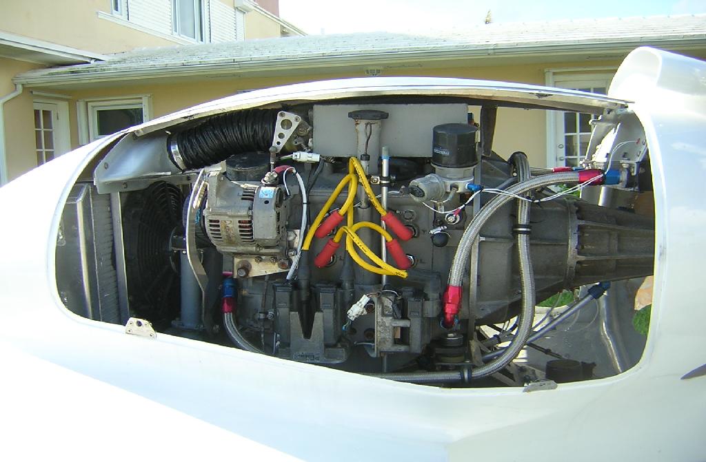
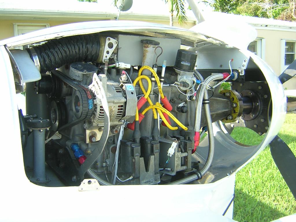
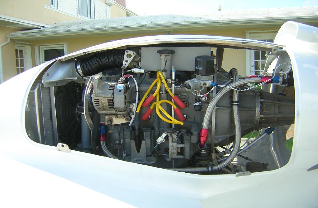
I have my Renesis engine, built by Bruce T., which looks great. I'm
working on the mounts. Your previous recommendation was to make an
oil
pain with a Scherz-type beam under the front of the engine (pusher
config.), to extend out about 24" total to pick up the prop. torque.
For various reasons, I'd like to have this beam just bolt up under a
flat section of the oil pain (instead of being welded to the thin oil
pan metal).
If this beam bolts up under engine using the oil pan bolt holes, it
must
have four sides (unlike most of the current Scherz beams). I can
get 2"
square tube in both SS and 4130, but the wall thickness is .065, a
little heavier than Jerry's beam (but still only 3lbs.) My
calculations
show this is way stronger than the loads you mentioned. Since this
is a
pusher with the engine right behind and above the cockpit, I'd like
the
mounts to not completely fail even with much higher loads.
A smaller square (1" or 1.5") might be OK, but it would be smaller
than
the 2" diameter of the rubber mounts, and there will be a problem
with
the pan bolt holes (see below). I can also get 2x1" tube in .065,
which
would save some weight but lose 1" of vertical height.
I can get 6 oil pain bolts through a 2" beam, even though the outer
two
are stepped back (not in line) with the others. This seems good, but
limits me from using a smaller beam that would only get the first
four,
in-line bolts.
My questions are:
1. The current oil pan bolts are only 5mm, but I will have 6 of them.
Should I tap these holes out to 6 mm for extra strength? I can get
6mm
x 1.0 grade 12.9 cap bolts and the drill hole size will work.
2. The beam will need holes on both the top (5 or 6 mm for the bolt
itself) and the bottom (8-9 mm to pass the bolt and wrench through).
Would these 6 holes on the top and bottom of such a beam
significantly
affect its strength?
3. Considering the bolt holes, would a smaller beam (such as 1"
high, 2"
wide) be adequate for the front mount?
4. My welder says he can do the oil pan a lot easier if the rear
mounts
are not an integral part of the pan, but a separate beam. This beam
would only have about a 1.5" cantilever, but a much greater load.
Would
any of the above considerations apply to a rear beam as well?
Thanks,
Scott Gettings
We never advocated welding the front Schertz beam to the oil pan
Scott. Or
at
least I did not. That is also not to say it won't work.
However don't reject thin sheet steel out of hand. It will take
loads if
properly applied. If you weld the rear MM ears to a curved peice of
.065
4130
and then weld that to the oil pan it will be way strong enough to
take
the 50 pounds of load experienced at the rear mount. Way over kill
in fact.
In your case the front mount.
I don't know what idiot started the nasty rumor that sheet metal oil
pans
will
take no load. It is an out an out lie.
I don't think you are going to find 4130 rectangular tubing anywhere
near as
large as the 2" by 3" Schertz beam Jerry sells. At least I have not
been
able to
find it so far. Since strength goes up with at least the square of
the
dimensions Jerry's S beam is probably four times stronger than
anything you
can
buy off the shelf with near the same wall thickness and weight.
The other factor is there is near zero torsion on a Schertz beam so
a closed
section is not required. "I" beams are not a closed section nor are
channels.
Both will take considerable bending loads to say the least. However
if you
feel this is important I am sure Jerry will weld some 4130 sheet
metal on
the
bottom to close the section and make it torsional stiff.
Tapping it out to six mm bolts won't hurt. You could also add these
clips
shown in the 3D which will make the assemble stronger for gyro
pitch loads.
----------------------------
For what it's worth, My beam mount is a piece of 2"x1" .065
rectangular
stock, with bolts through the beam to pick up 6 bolts. I also have a
set of
'ears' to pick up a bolt further back on the oil pan.
If you go this route, I recommend welding in spacer tubes between the
surfaces of the rectangular tubing so that you can properly torque
the
bolts, otherwise the rectangular tubing will have a tendency to bend
inwards.
If I were doing it over, I would use one of Jerry's bent up beams.
Bill Schertz
KIS Cruiser # 4045
--------------------------------
Thanks for the new pictures.
Nice oil pan Bill.
Paul Lamar
Beautiful, work, Bill. Thanks for all your research on this issue.
And thanks, Paul for letting this thread live on to answer my dumb
questions!
Bill, did you use larger bolts than stock to attach your beam?
My previous post was in error -- the stock Renesis oil pan bolts are
6
x 1.0 mm, round socket (alan head) bolts.
Since the bottom of this beam is in tension, would it be acceptable to
have holes in the lower surface just large enough to pass the bolt's
round head through, and have the bolts just grab the upper, 'inside',
surface of the beam? Getting washers on them would be tricky, but
possible. If not, the welded spacers seem very reasonable for larger,
hex-head bolts that went all the way through. In my application, a
closed beam would be a little easier.
Scott Gettings
Sure Scott that will work fine. What the stock beam is two channels
back
to back. Think of the bottom slot as a way of getting the bolts in
there.
Kind of tricky no doubt. If you closed it then added spacers welded
in would
work fine and the strength of the beam would go way up.
If this is the configuration you are working with the six G vertical
shear load of 1800 pounds on the two rear brackets assuming the pan
is welded from .049 4130 sheet is 900 pounds per side or 450 pounds
each vertical sheet ear. The .049 4130 sheet ear is 4.5 inches high
so that is .22 square inches for each interface. Assuming the ears
ARE NOT welded to the flange. Welding the ears to the flange will
make them stronger yet.
The shear stress level is then 450 divided by .22 square inches or
2,045 psi.
Nothing for 4130 as 4130 will easily accommodate 60,000 psi or 30
times
as much. One rubber bushing on one side could disappear and the oil
pan would still survive multiple hard landings.
When the beam is on the front of the engine like this the beam loads
are 90%
prop torque or about 400 ft pounds or 4800 inch pounds. The bushing
spacing
is roughly 22 inches center to center so one bushing will see +110
pounds
and the other will see -210 pounds.
Assuming only the outer pan bolts are taking the tensile load due to
the torque and there are no gyro clips it is seeing 4800# / 12" or a
tensile load of 400 pounds. The other side is in compression so there
are no loads on the bolts from this source. Six mm is .2362 diameter
so for our purposes the root of the threads we will assume are only
.2 inches. The root area would then be .031416 square inches. 400
pounds divided by 12,800 psi. Well within the capabilities of the 6
mm bolt. An 8 mm bolt would make it some what more conservative 9,600
psi.
If the S beam is welded to the pan then the loads are shared by
several bolts
and no gyro clips would be needed. It would then be necessary to do an
FEA to estimate the stress but in no case would the bolt stress be
higher than what we just calculated.
This is eliminating the anti torque contribution of the rear motor
mounts. This is a simple analysis.
If one needed a more detailed analysis one would have to take into
consideration the hardness of the rubber bushings involved. Things
would be
easier to analyze if there were only one rear mount. If we have
redundantly constrained situation here with four rubber mounts. In
that case the one
rear mount would take 100% of the landing load the the front s-beam
would
take 100% of the torque load for calculation purposes. Nothing in here
is the least bit marginal. Way over kill no matter where you look.
You need an oil pan anyway you might as well put it to work and
save some weight.
Paul Lamar ...No rotor no motor.
Thanks again, Paul. This answers a lot of questions.
Building the pan itself seems the biggest issue. I'll see what Ed or
my local resources can do with this. My aerospace machinist friend
wanted to make the pan base out of 1/4" steel, weld it, then mill it
down perfectly flat after all the welding was done. Ouch!
Scott Gettings
Hang on for a couple of hours. I am doing a new 3D. I think we can
make it out of aluminum and not use the S beam at all. It would be a
shame to waste it on
this as the stresses are way down on your over all oil pan and front
mount.
There is more stress on the pan bolts than any other single item I can
find.
Fatigue is not a factor. I think we can bend the whole thing up out of
.063 6061 T6 and tig weld it up. Should be about half the weight of
.050 4130 and cheaper too. .050 4130 sheet steel is about two pounds
per square foot and
0.063 aluminum is .889 pounds per square foot.
I am sure Ed Klepeis can do a fine job. I just got a CC auto darkening
welding helmet for my tig welder for Christmas. With a couple of
months of practice and several hundred pounds of wasted good aluminum
even I could do it :)
One of my New Years resolution is to practice my tig welding.
Paul Lamar ...No rotor no motor.
Thanks again, Paul. I know about the aluminum welding thing. I just
get lots of big holes, so I leave it to those who know what they are
doing! I can't wait to see what you come up with.
For safety reasons, I'm a little concerned because the engine sits
right behind the upper wing tanks and above/behind the cockpit. For
this reason, would it be wise to have the strength of the mounts in a
down-and-forward direction be more in the range of 20G? 300lb x 20G is
6,000 lb, or 1,500 lb per mount if it were shared equally.
The front mounts will be built on a heavy section of the wing's shear
web, but there are fuel tanks right underneath. If the front mounts
failed, the front of the engine block and/or pulleys would probably
penetrate this area. The rear structures could collapse quite a bit
without damage, but not the front. (I already static-tested the rear
mount composite/wood bridge structure to 4,000 lb vertical load without
a problem.)
Some bending might be OK in a high-G situation, but I'd rather pick up
a little extra weight than have the mount fail in an otherwise
survivable crash. If it makes sense to factor any of this into the
mounts, I would appreciate it immensely.
Scott Gettings
--------------------------------------------------------------
The best material for that is Kevlar. P&W, GE and RR use it to contain
burst turbo fans. Get yourself enough of it to slather on five or more
plys on the top and rear of the upper fuel tank.
The structure to take 20G's
would be way too heavy as you would have to beef up everything half way out the
wings and all the way back to the tail and all the way up to the nose. Even a
steel cable around the engine would not help as the cable anchor would fail. I
doubt seriously if you saw that many G's in a head on crash you would be crushed
by the top wing and the rest of fuselage structure let alone the engine. The
engine would probably go right over the top of the top wing anyway because the
CG of the engine is higher than the wing. That would help you survive as there
would be less mass behind you. Unfortunately this is a fact of life with pusher
airplanes. Not enough structure ahead of you to collapse and mitigate the G's.
You would be better off on spending the money and weight on a ballistic parachute.
Here are some pictures of the Glass Goose or Sea Hawk so the new guys have a
feel for what we are talking about here.
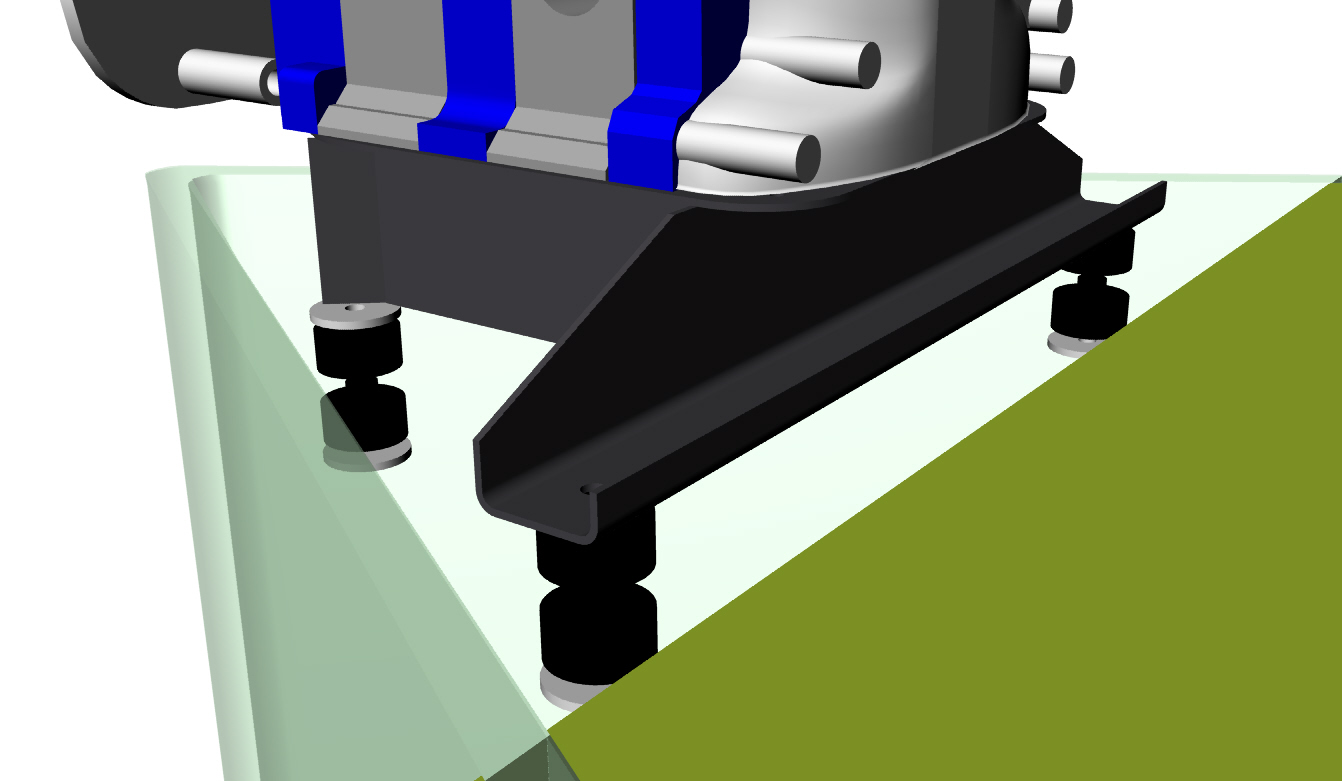
Anyway be all that as it may here is the 3D on the all aluminum version.
Paul Lamar ...No rotor no motor.
The Rotary Engine NewsLetter. Powered by Linux.
ACRE NL web site.
http://www.rotaryeng.net
Copyright 1998-2005 All world wide rights reserved.