>
>
> I have been out of the loop for a few days. This morning I read the
> series of posts on the P-can system proposals. I must weigh-in strongly
> against the P-can concept for the rotary (in an aircraft). It will lead
> to premature failure of the O-ring housing seals. Here is why.
>
> As Paul has said many times, the devil is in the details. The O-ring
> seal is a wonderfully simple type of self-pressurizing seal. But, it is
> not as simple as it seems. As a self-pressurizing seal it must deform
> under pressure to seal properly. As you can see in the cross section
> drawing I've attached, the ring is forced by the fluid pressure against
> the three confining surfaces and the deformation of the ring creates the
> seal. O-rings work very well as long the surfaces are clean. Now
> imagine reversing the pressure differential so that the O-ring is forced
> to the other side of its groove. Now the required deformation is in the
> reverse direction. O-rings do not work very well under alternating
> pressure differences like this. The O-ring surface degrades from
> abrasion. And, more importantly for the rotary housing seals, unseating
> the O-ring from its sealing surface allows contamination of the sealing
> surface by particles in the fluid. In the case of the housing seals,
> when the engine is running the seals are forced outward, away from the
> rotor. The P-can pressure would force them inward during the entire
> time the engine was not running. I think this would quickly lead to
> seal failure. Of course, the normal auto type system places a reverse
> pressure on the O-rings upon shut down when the engine is hot. But,
> this pressure is only present for a short time until the engine cools
> enough to cause the partial vacuum that allows coolant to flow from the
> overflow bottle.
>
> In summary, the design should insure that during quiescent periods, the
> pressure differential across the housing O-rings is essentially zero.
> This requirement pretty much requires an overflow bottle at atmospheric
> pressure.
>
> I suspect that we will find that Dave Leonard's recent loss of coolant
> was caused by catastrophic O-ring seal failure brought on by
> contamination of the seal surfaces with stop-leak when there was a
> pressure reversal on the O-rings.
>
> Respectfully submitted,
> Aubrey
-------------------------------------------------------------------------------
I see what you are saying.
I cannot remember the seal combinations between the housings and rotor
sections to make a comment
I'll have to look at some reference diagrams and clearances first.
Regards David Gaze
Here are some picture David. A lot of the guys are now going with
the Teflon encapsulated silicone O-rings which seem to hold up much
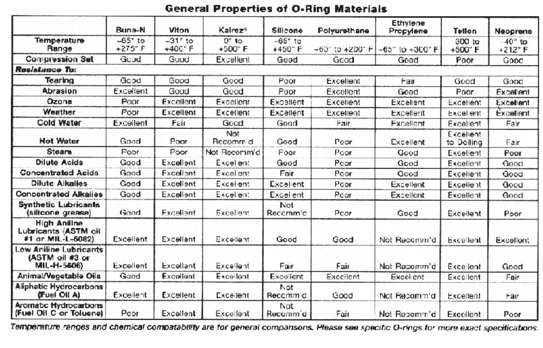
better than the stock Mazda O-rings. The Teflon being good up
to 800 F and inert to the vast majority of chemicals. Also
cheaper than the stock O-rings.
http://www.creavey.com/
I will outline what we are talking about.
There are four coolant sealing O-rings per rotor housing.
Two outer and two inner.
There are also four oil sealing O-rings per rotor. Two on each side of
the rotor proper. These are located on the flanks of the rotor.
Two per side.
Teflon encapsulated silicone O-rings are the best there is for this
application. Teflon is about the most inert material you can
find and it is resistant to most known chemicals. Unfortunately
it is not rubber like and that is where the high temp silicone
rubber core comes into play.
http://www.creavey.com/
> 1. Inner coolant oring -
>
> circumference = 28.625
> diameter = 9.111
> slot depth = 0.062
> slot width = 0.141
> section size = 0.098
> 2. outer coolant oring -
>
> diameter = 11.340
> slot depth = 0.062
> slot width = 0.110
> section size = 0.093
This is critical! The proper section size is .093. Not 3/32
as a 3/32 O-ring is bigger in section size than .093.
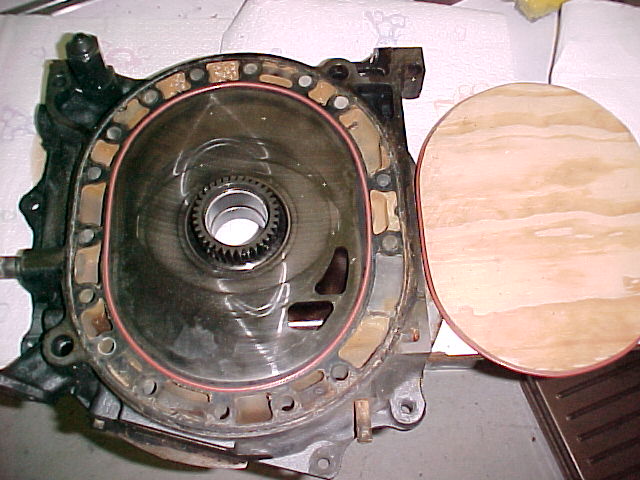
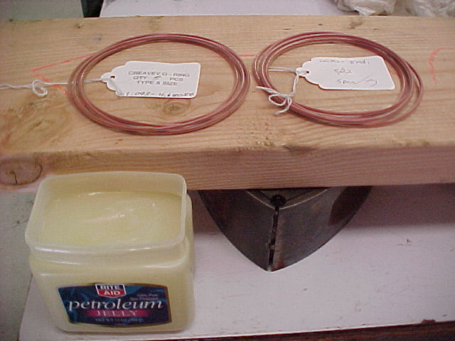
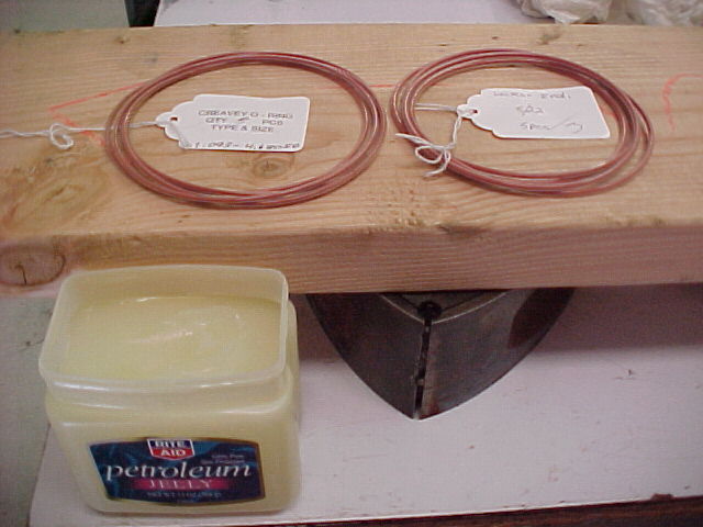
The TES O-rings are stiffer than the stock O-rings. It is harder
to get them to lie in the groove. Even with Vaseline. When you buy
them they don't come flat. I found that using a plywood
form to pre set the slightly under size TES O-rings for a few
days works well. Here is a picture.
--------------------------------------------------------------
Oil O-rings.
I checked the installation of the oil O-rings with the new
sizes I got from Creavey. They worked perfectly and were
very easy to install. You will need a little O-ring lube
and a 2 by 8 to install them. They were also easy to remove
with no signs of distortion.
One of the secrets is if you reuse the old oil scraper rings
they must be spotlessly clean inside and out. Soak them
in carb cleaner for a few days. If you use new scraper rings
this will not be a problem of course.
The second thing to watch out for is don't nick the
rotor wall between the two scraper rings when you remove them.
Very very important!!
These can be the same or just a little more than the
stock oil O-rings from Mazda.
The proper oil O-ring sizes are:
0.093" section 4.68 inch ID
0.118" section 4.33 inch ID
I can vouch for the quality of the Creavey O-rings but some
of those water TES o-rings from Mcmaster Carr I have seen
are not as good. This is not to say they won't work. They just
don't look as good around the joints as Creavey O-rings.
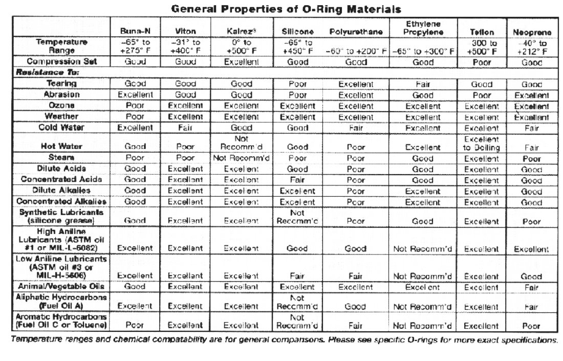
Viton is good only to 400 degrees F. The center of the rotor runs
as high as 500 degrees F. I think 400 degrees F leaves's too
little of a safety margin when 500 degrees F is available
in TES O-rings at the same price probably.
************************************************************
How-to-measure.txt
Here is how to double check my work. We will do a little reverse
engineering.
The O-ring grooves are two half circles connected by straight sections
to form sort of an oval.
Measure across from side to side on the end housing to the inner edge
of the O-ring groves This then is the inner diameter of the half circle.
We will call this dimension SSL. For the inner O-ring this diameter is 7.5"
Outer diameter is is 9.75". These form two circles of 23.562 circumference
and 30.63 circumference. C = D X Pi (3.1416)
Measure the distance up and down to the inner edge of the O-ring grooves.
For the inner O-ring groove this dimension is 9.75 (confusingly).
Outer o-ring groove is right on 12 inches.
We will call this dimension VL for vertical length. VL-SSL gives us
the length of the straight sections. We have two straight sections
9.75- 7.5 or 2.25 inches in length for the inner o-ring slot
and 12 - 9.75 or 2.25 for the outer O-ring slot straight sections.
There fore the inner circumference is 23.562 + 2.25 + 2.25 or 28.062".
Close to the number we got below. Divide by 3.1416 to get the
equivalent diameter.
For the outer o-ring slot the circumference is 30.63 + 2.25 + 2.25 or 35.13.
Also close to the number we got below.
Now to be real precise you must repeat these measurements for
the outer O-ring slot grooves.
Or we could merely take these numbers as the center line
numbers or OD numbers. In any event you want to err on the small side
as you are going to cut pieces of plywood the exact size
of the inside wall of both slots and slip the o-rings over
this plywood form for for a few days so they will take a set.
Other wise you will play hell getting the o-rings to lie flat
in the grooves when you assemble the engine.
Paul Lamar ...No rotor no motor.
The Rotary Engine NewsLetter. Powered by Linux.
ACRE NL web site.
http://www.rotaryeng.net
Copyright 1998-2005 All world wide rights reserved.