Paul,
With all the talk about different systems, here are a few shots of how
mine is laid out.
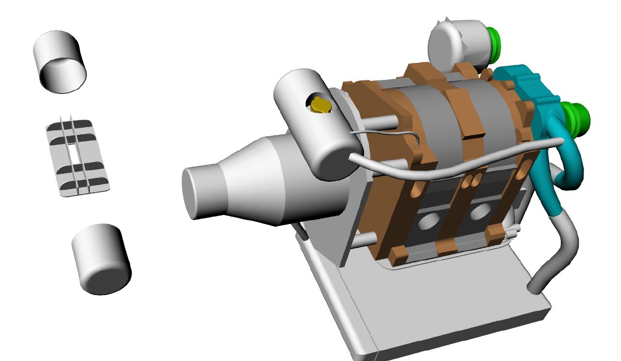
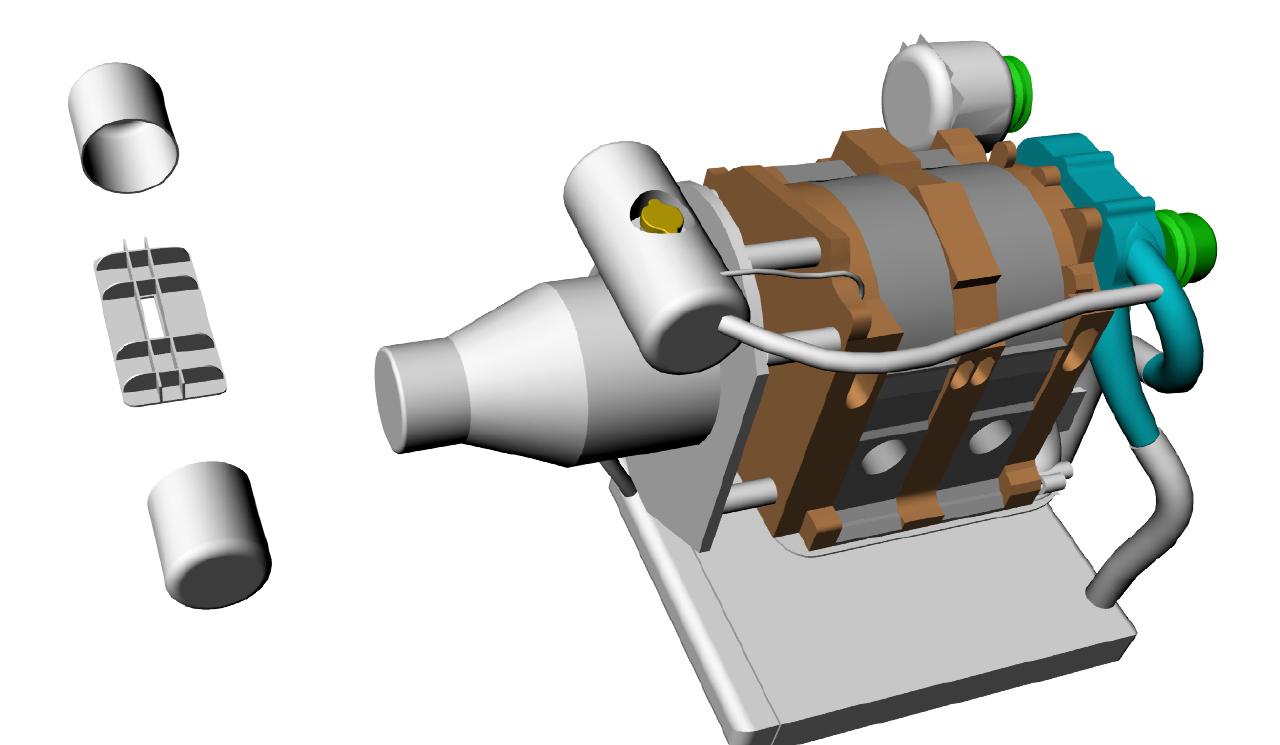
Rear.jpg shows the return path from the front radiators, and a vertical
standpipe with a pressure cap installed. The pressure cap will be at the
lowest pressure in the system, being on the suction side of the pump,
and having about 12" of (negative) head relative to the suction
branch-off point.
There is a hard-plumbed (AN-4 ) line leading from the pressure cap
relief over to a P-bottle on the cool side of the engine. You can also
see my heater hoses (both supply and return). There is a check-valve on
the return line and a shutoff valve on the heater supply line.
Coolant_bottle.jpg shows the overflow reservoir. It is a piece of 3"
tubing with a pressure cap on top, a brass Shrader valve, a liquid level
sensor, and the entrance to the bottle is on the bottom, connecting to
the AN-4 line from the engine.
Left_front, Right_front, and Return_rhs just show the overall flow
plumbing using 1-3/8" tubing with wiggins fittings where possible. The
silicon hose connecting the two rads in parallel have Breeze constant
torque clamps.
Operation: System is filled from the pressure cap on the engine. Care is
taken to get as much air as possible out of the system, Then fluid is
added to the reservoir can, ~10 psig is added through the air valve, and
the pump operated. Free air should rise into the stand-pipe, and as the
fluid expands, be forced into the pressure reservoir. Upon cooldown, the
pressure in the can will force liquid back into the engine circuit.
I plan to operate with a 'small' pressure in the reservoir, ~ a 10psi
cap on the stand pipe, and similar on the reservoir.
Bill Schertz
KIS Cruiser # 4045
Looks good to me Bill.
Why only 10 psi pressure release caps?
The 10 psi pre charge pressure is probably a good idea.
Where does the pressure can tie in?
Can you sketch a schematic of what is connected to what
and where marked with pipe sizes?
I think the standpipe on the pump input side should have a sealed
cap and the pressure tank should have a pressure release cap.
Mount the pressure tank as high as you can get it and vent
it to the front of the block.
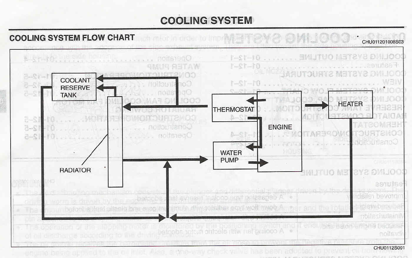
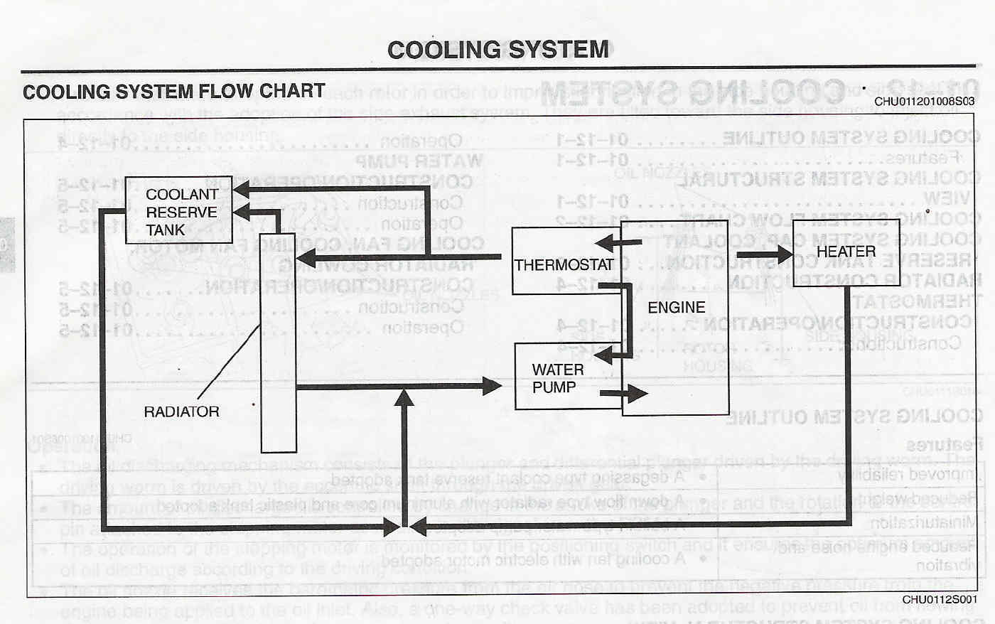
Looks like you have room over the PSRU for Mazda RX8 style pressure
tank with air separator.
--------
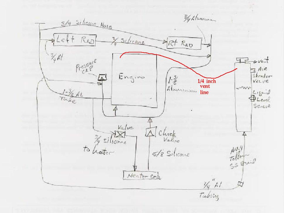
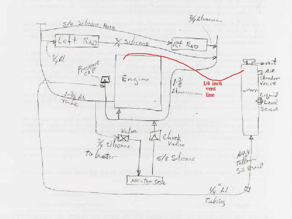
Schematic enclosed.
10 psi cap on stand-pipe + 10 psi on Reservoir = 20 psi
Pressure can ties into standpipe vent.
Bill Schertz
KIS Cruiser # 4045
Looks like it will work fine as is. I would add a vent line from the
front of the engine as that is where you are likely to get
an air or steam bubble on a sustained climb. The 1/4 inch line out
of the bottom of the pressure can to the pump inlet meets the
Mazda criteria.
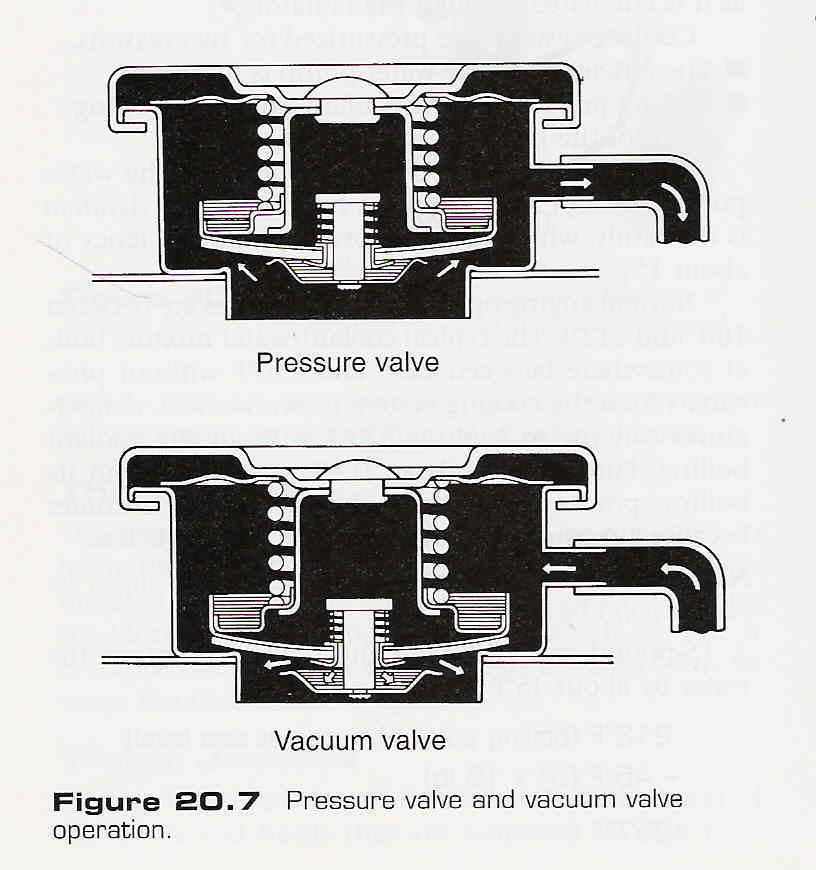
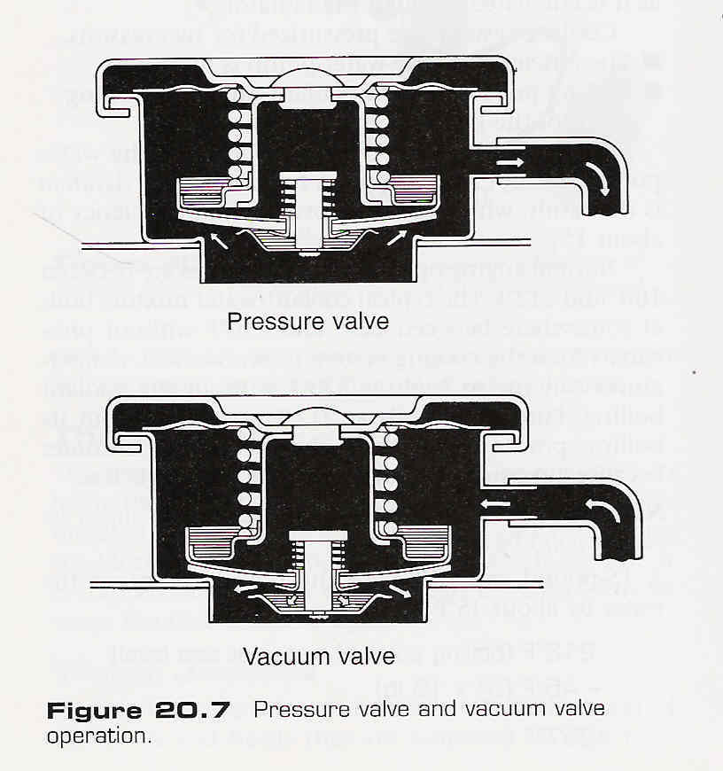
The pressure caps don't work in series. The upper seal will not
sustain anything over a few psi. Test it to make sure.
I would seal the stand pipe with a screw on cap to make sure it does
release pressure and coolant before the one on the pressure
can with expansion air in it. Vent the top of the stand pipe
to the top of the pressure can.
It would be nice if the fluid level in the expansion tank
was higher. Above the level in the block ideally. That implies a larger
diameter flatter tank like the Continental.
Consider doing another horizontal tank and placing it above the PSRU. Looks
like you have room up there. Then the air will naturally collect up there
in a climb.
Paul Lamar ...No rotor no motor.
The Rotary Engine NewsLetter. Powered by Linux.
ACRE NL web site.
http://www.rotaryeng.net
Copyright 1998-2005 All world wide rights reserved.