Paul,
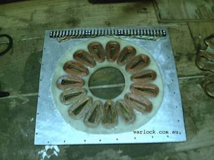
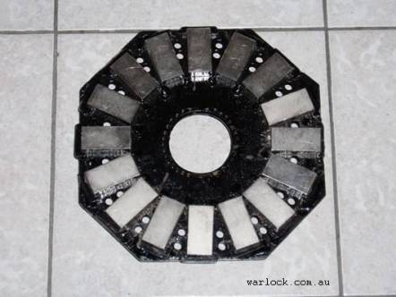
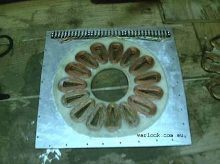
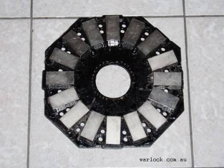
I pressed enter and it sent.... Here are a few pictures from home
built wind generator. I think I like the radial design(RevMaster and
Harley) better though. The parts are contained better. The axial
design has the surfaces close together and vibration combined with
high rpm could cause the surfaces to meet. I think that the radial
design would have less chance of that and easier to balance.
If we plan on making a toothed wheel with inductive pickup part of
the design then the flywheel style alternator will need to go onto the
opposite end of the shaft. The magnetic field of the alternator will
interfere with the timing pickup. It looks like Renesis has the
toothed wheel behind the pulley.
The DIY wind power generators I have seen are very close and are
called "axial flux" The coils are turned were they look like a bunch
of 'O's making
petals to a flower. Same with the magnets. Three disk sandwich;
magnet, stator and magnet. They hand turn the coils and embed them in
epoxy resin to seal it from the elements.
The places for the alternator:
Prop flange
prop rpm
low rpm is easier balanced
Highest vibration area?
part of the split PSU and still in design phase
moment is wX
furthest from compass
Between the planet cage and fly wheel - in the bell housing
engine rpm
part of the split PSU and still in design phase
moment is w(X - ~14")
Pulley side
engine rpm
Move toothed wheel to flywheel - minimal moment change
Could be part of an accessory case design(oil scavenging, vacuum)
Pulley (water pump) would have to be integrated and limits
diameter and offset.
moment is w(X - ~34")
closer to compass
--
Blake C. Lewis
The Rotary Engine NewsLetter. Powered by Linux.
ACRE NL web site.
http://www.rotaryeng.net
Copyright 1998-2005 All world wide rights reserved.