Paul, I saw your comment to Mark about me being able to supply
louvers. I did make one set, that turned out o.k. sort of but not
ready for prime time. They were a learning exercise. I made the
louvers by folding .032 aluminum into a flap shape and then riveting
this to a 5/8" dia. 4130 tube that served as a spar/axle. The rest of
the details are not important at this moment.
I think a better louver could be shaped from foam which is then fg'd
to the spar. It is on my to do list, but I have not pursued it
further.
How to operate the louvers is not a problem. I have,
mentally switched back and forth between attaching the louvers to the
radiator or to the cowl. The prototype has them attached to the
radiator but this will exert (unknown) forces into the rad,
especially when the louvers are extended. This worries me and is one
reason I am thinking of building them into the cowl. Another reason
is that it is necessary to have a clean, leak free interface around
the perimeter of the louvers and the cowl. This is much easier if
they are just glassed into the cowl from the get go.
The louvers require only about 3/4 inch space, max, between the
radiator and the cowl. Just enough to clear the axles. Of course
when they are open the space goes to infinity. I am against non
adjustable louvers unless the thermostat is retained.
Jerry
Thanks for your thoughts on this Jerry.
Sealing is not essential.
I think your first design was a bit overkill. 1/2 inch .035 4130 tubing
and .025 aluminum should be strong enough pop riveted together. A bit
cheaper too. Some people hate gup and prefer to work in metal.
I prefer metal but gup is not all that hard :)
Here are some shots of the automatic type cowl flap using a AC VW engine
thermostat. This idea goes way back to Tony Bingelis book Fire Wall
Forward.
Paul Lamar
So Jerry, I never did quite figure out whether you were going to fly
that home-made oil pan or not. I'll have to dig out the photo of it
again, but it is looking like the shape I will need for my install. So
if you are not flying it, I probably want it...
I agree on the flaps being part of the cowling, not mounted to the rad.
I was pondering it last night & came to the conclusion that a metal
frame glassed into the rectangular cowling cutout would stiffen the
cowling nicely while serving as a platform to attach flaps.
I am worried a bit about how much weight this is going to add at a
really forward station.
Mark Supinski
Lets see three flap sheets 18 inches wide by 16 inches long by
.025 is 7.2 cubic inches or .72 pounds each. 2.16 pounds for three.
Flap is 18 by 8 roughly. Clamp the flap between boards
and inject urethane foam from the hardware store.
.035 wall half inch 4130 tube .1738 pounds per foot. 4.5 feet .78 pounds
total for 4.5 feet.
1/2 inch square .035 wall 4130 tubing .2213 pounds per foot
18 by 24 or 7 feet long 1.55 pounds for the frame.
2.16 + .78 + 1.55 = 4.49 pounds total. Carbon fiber
flap skins and foam might save a pound.
Well worth ten MPH on the top end and a warm engine.
--------------------------------------------
ops I forgot to subtract the weight of the cowl material
removed by cutting the large hole.
You could save another pound by making the frame out
of a carbon fiber flange around the hole in the cowl.
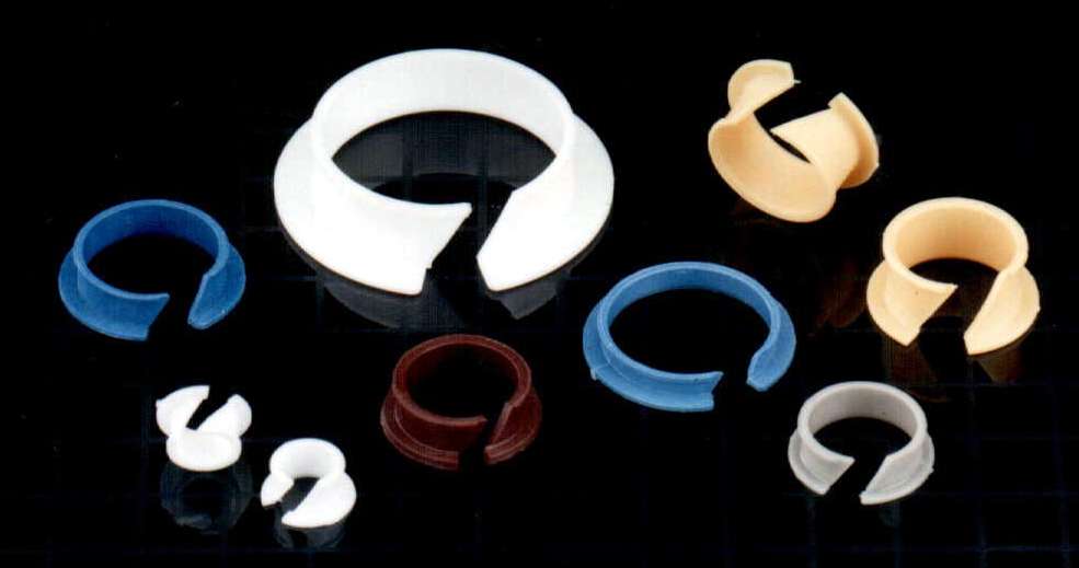
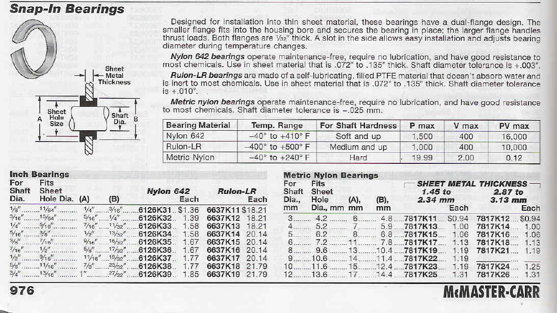
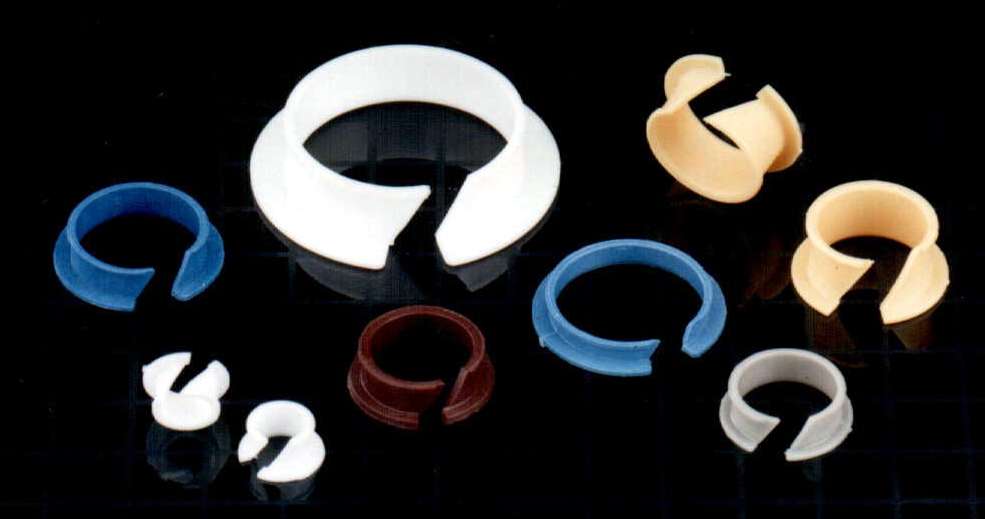
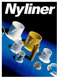
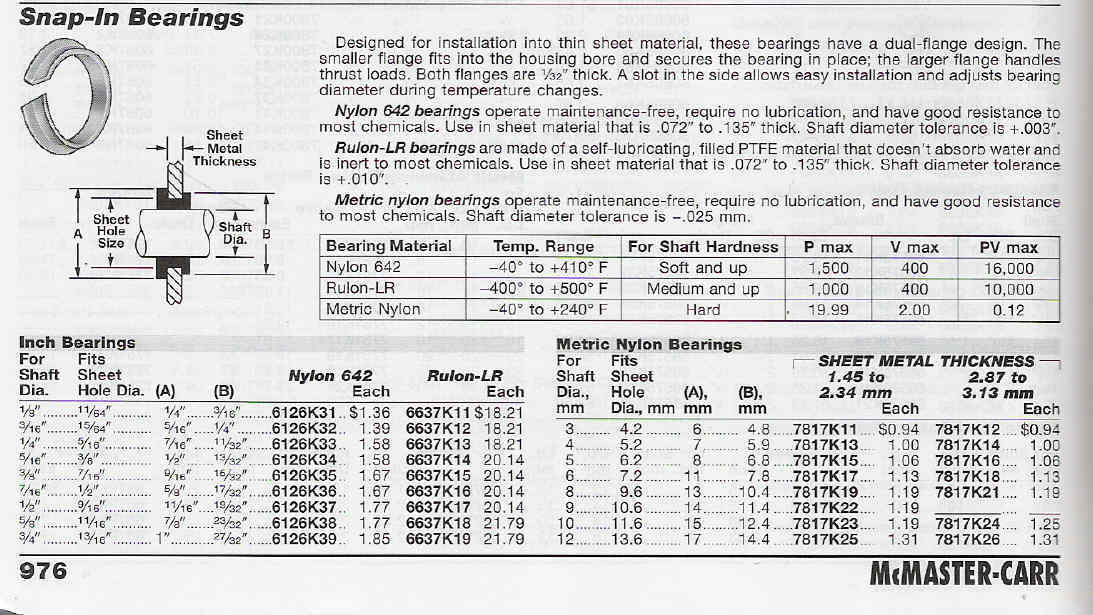
Here are some super light weight super cheap nylon
bearings that will work in the carbon flange.
--Name: Thomson Industries Inc.
Address: Two Channel Dr.
City: Port Washington
State: NY
ZIP: 11050 2214
Country: USA
Phone: 888-288-8298
FAX: 516-883-8937
http://www.thomsonindustries.com
Paul Lamar ...No rotor no motor.
The Rotary Engine NewsLetter. Powered by Linux.
ACRE NL web site.
http://www.rotaryeng.net
Copyright 1998-2005 All world wide rights reserved.